Hacking Together Wi-Fi Elegance and Performance - Part 1
Concept
Since around the 802.11ac (Wi-Fi 5) era, all the new networking gear has been hideous. Bulky and clunky designs, one single LED indicator and antennas that look like a spider are not it IMO. And quite frankly, I’m okay if the astronauts on the space station can’t pick up my SSID with their iPhone. I’m on a mission to change that without sacrifing (too much) performance.
NETGEAR’s 802.11g and 802.11n designs have held my heart, somewhat resembling the original unibody MacBook. Slim, sleek and stylish without being annoying.
 WPN824 Positioned Vertically - source: https://www.netgear.jp/productsimg/images/product_WPN824.png
The WPN824 (non N), WNDR3300, and WNDR3400v1 also had a fun feature – a ring of 7 or 8 LEDs in the blue dome on top, representing activity on each antenna. Truthfully, I think the only model that actually used the dome LEDs to show which antennas were in use was the WPN824, as it was based on a design from Video54. The WNDR3300 and WNDR3400v1 likely just blinked on each radio’s tx/rx, like a front panel LED indicator. I don’t think Broadcom, who designed the chips in these two, actually implemented blinking an LED based on the antenna usage in the MIMO array.
Further for this project, implementing the true antenna utilization functionality will be out of scope for a few reasons, most importantly being that we are not spinning our own hardware/drivers. Instead, we will be taking a shell from a WPN824v2 and a BananaPi BPi-R4 with an 802.11be chip, modifying the device tree and LED behviors, and making the board fit into the shell with functioning front panel LEDs one way or another. I’ll dub this the WPN824BE.
In part 1, we will be figuring out how to Make LEDs Great Again.
WPN824 Teardown
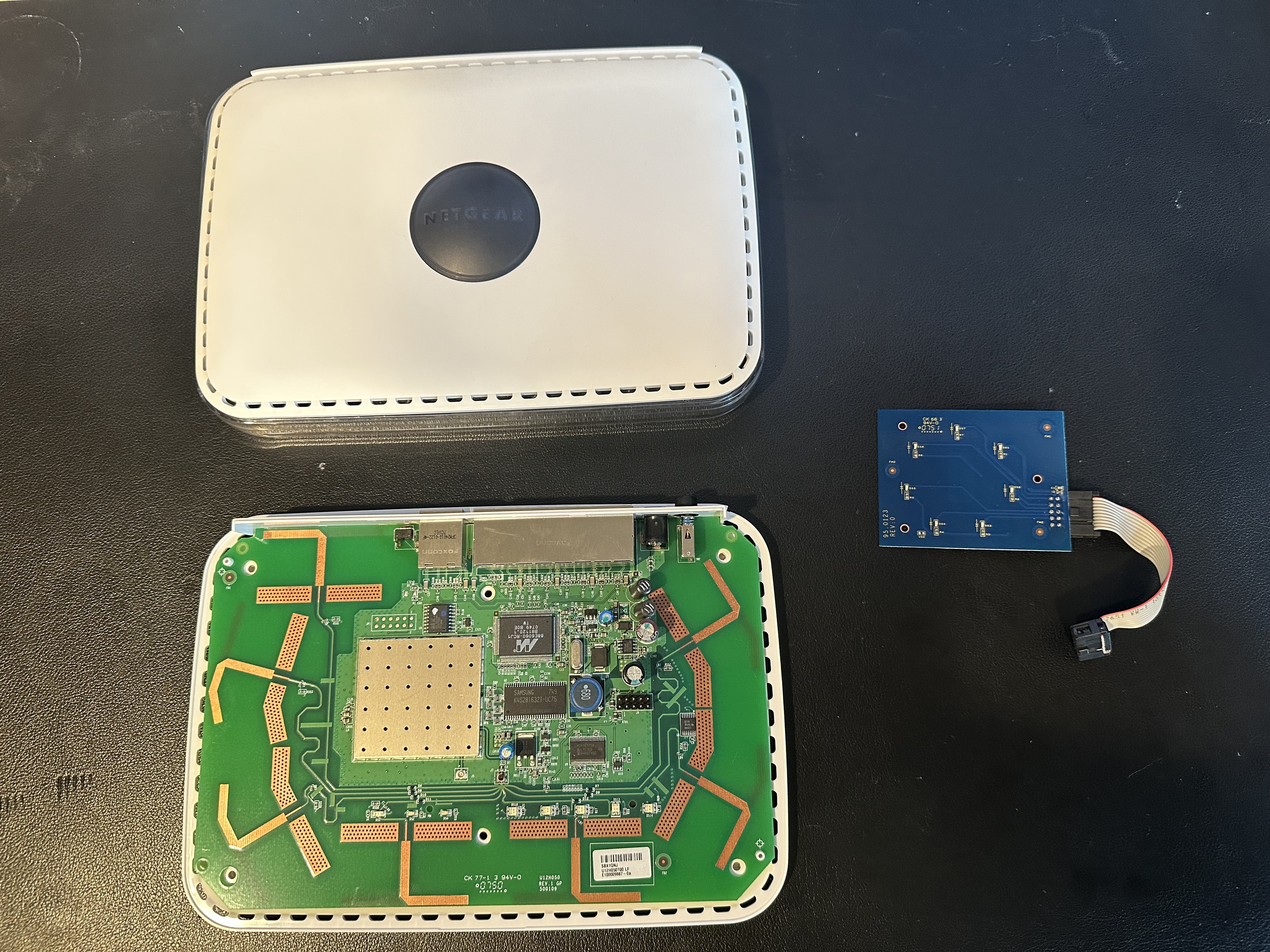
Let’s start with a teardown of the WPN824. There are 6 TR8 secrews on the undersize, 4 of which are under the rubber feet. Remove those and carefully lift the top off.
 WPN824 Teardown
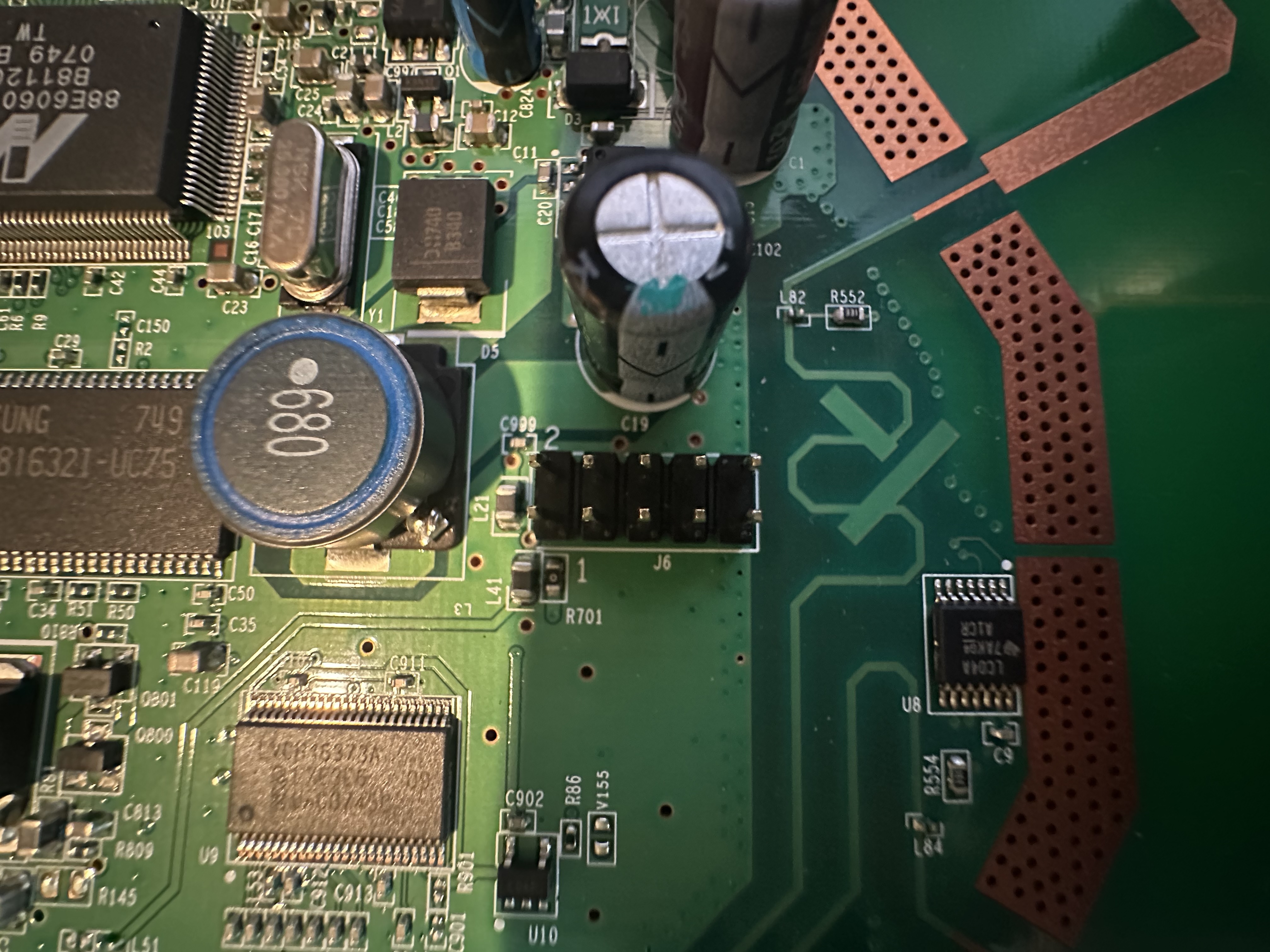
The LED board is connected to the 10-pin header on the middle-right side of the board.
 WPN824 Dome LED Header
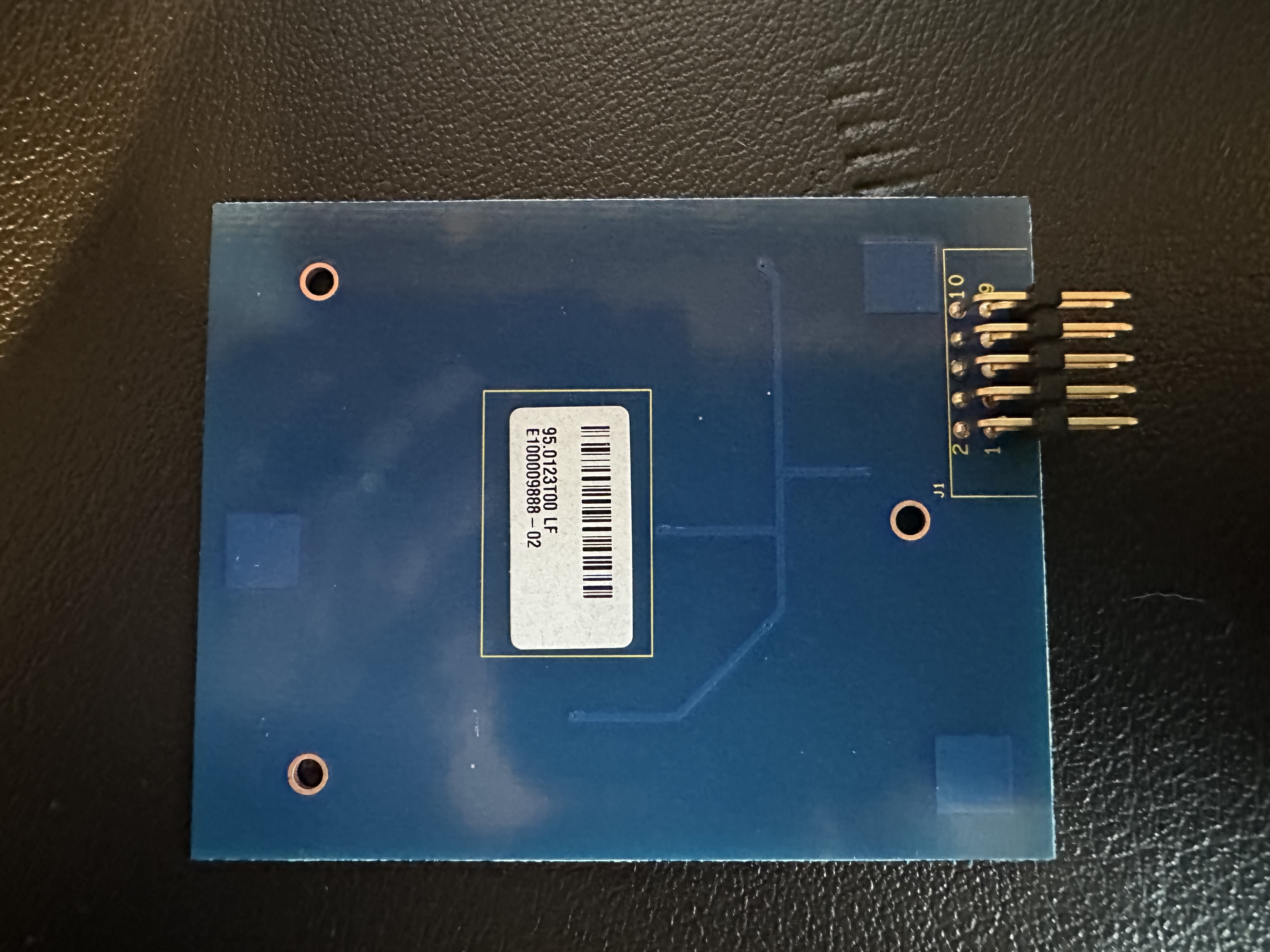 WPN824 Dome LED PCB Bottom
A multimeter can tell us what each pin on the router PCB is doing. First, with the power off, identify ground by setting the multimeter to continuity mode and touching the black probe to a grounded area, such as an RF shield, and the red probe to each of the pins. If it beeps, it’s ground.
Next, set the multimeter to DC voltage mode and power the router on. Touch the black probe to ground, and measure the rest of the unknown pins. We’re left with the following configuration:
| Functionality | PIN | PIN | Functionality |
|---|---|---|---|
| +3.3v | 1 | 2 | antenna |
| antenna | 3 | 4 | antenna |
| antenna | 5 | 6 | antenna |
| antenna | 7 | 8 | antenna |
| GND | 9 | 10 | no connect |
Pins labeled antenna are flucuating between 0v and +3.3v rapidly, indicating that there is supposed activity on said antenna. The others are self-explainatory.
Putting Theory to Test
This stage assumes you already have a vanilla OpenWrt install on the Bananapi BPi-R4. Let’s power it up and grab a 3 Female-to-Female jumper wires. The BPi-R4 has the following GPIO headers, where pin 1 is indicated by the white dot on the PCB:
| Functionality | PIN | PIN | Fuctionality |
|---|---|---|---|
| +3.3v | 1 | 2 | +5v |
| GPIO18 | 3 | 4 | +5v |
| GPIO17 | 5 | 6 | GND |
| GPIO62 | 7 | 8 | GPIO59 |
| GND | 9 | 10 | GPIO58 |
| GPIO81 | 11 | 12 | GPIO51 |
| GPIO80 | 13 | 14 | GND |
| GPIO50 | 15 | 16 | GPIO61 |
| +3.3v | 17 | 18 | GPIO60 |
| GPIO30 | 19 | 20 | GND |
| GPIO29 | 21 | 22 | GPIO53 |
| GPIO31 | 23 | 24 | GPIO28 |
| GND | 25 | 26 | GPIO52 |
Let’s connect pin 1 (+3.3v) on the BPi-R4 to pin 1 (+3.3v) on the antenna PCB, pin 25 (GND) on the BPi-R4 to pin 25 (GND) on the antenna PCB, and pin 18 (GPIO60) on the BPi-R4 to pin 2 on the antenna PCB:
| BPi-R4 Functionality | BPi-R4 PIN | LED Header PIN | LED Functionality |
|---|---|---|---|
| +3.3v | 1 | 1 | +3.3v |
| GND | 25 | 9 | GND |
| GPIO28 | 24 | 2 | antenna |
In the default state, an LED should light up on the LED PCB! Now, let’s figure out how to control it.
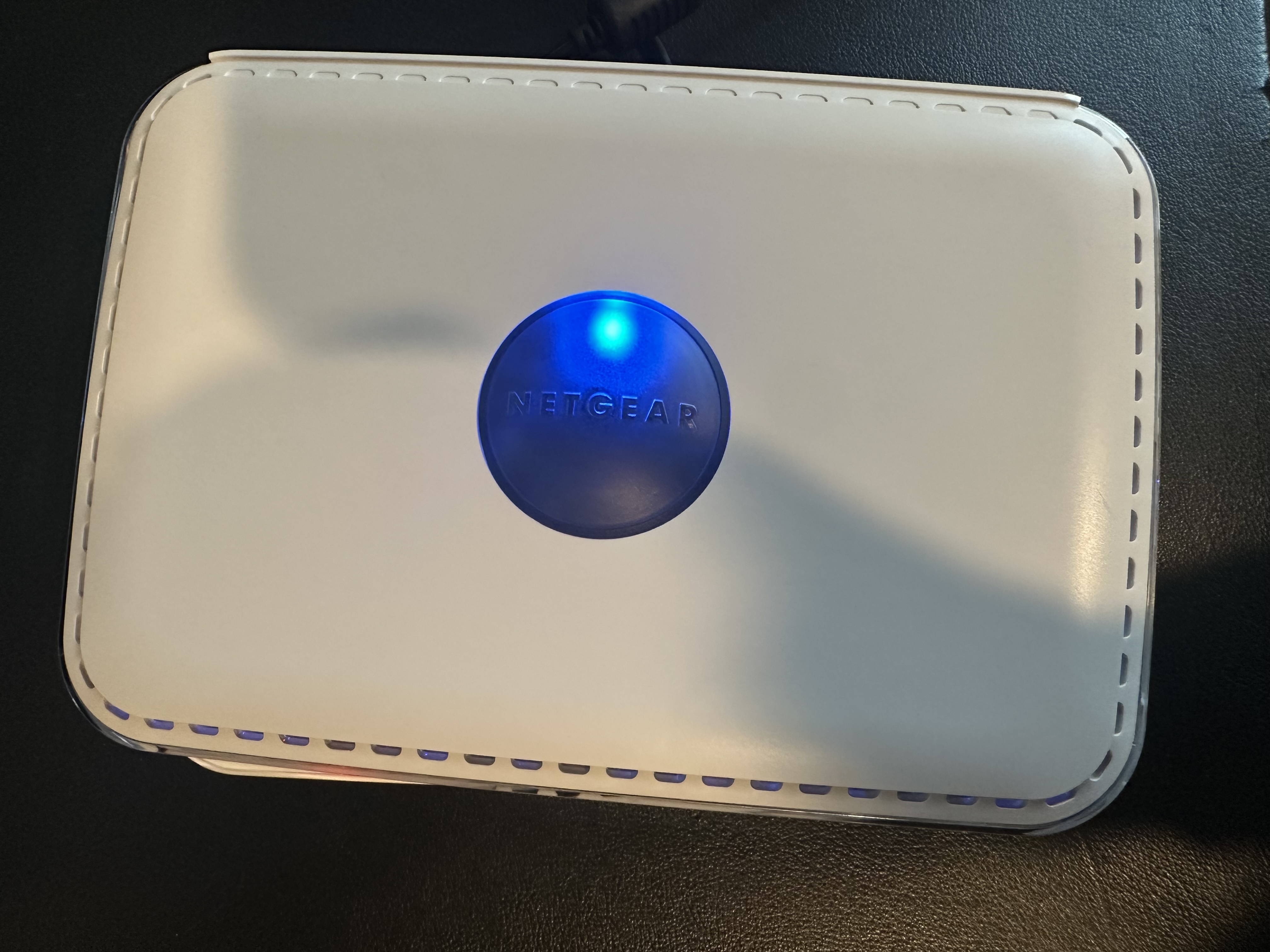 WPN824 LED Enabled
The GPIO base of the BPi-R4 can be found by looking in /sys/class/gpio:
1
2
root@OpenWrt:~# ls /sys/class/gpio/
export       gpiochip512  unexport
Here, it’s 512, as referenced by gpiochip512. Now, let’s enumerate all the GPIOs. Given that the BPi-R4 GPIOs reach 81, we can put reasonable a cap at 512 + 128 = 640:
1
2
3
4
5
root@OpenWrt:~# for i in $(seq 512 640); do echo "$i" > /sys/class/gpio/export;
done
... lots of the following...
ash: write error: Resource busy
... and more ...
But, we can now see all our available GPIOs:
1
2
3
4
5
6
7
8
root@OpenWrt:~# ls /sys/class/gpio/
export       gpio523      gpio540      gpio547      gpio569      gpio589
gpio516      gpio524      gpio541      gpio548      gpio574      gpio590
gpio518      gpio525      gpio542      gpio549      gpio580      gpiochip512
gpio519      gpio529      gpio543      gpio562      gpio585      unexport
gpio520      gpio530      gpio544      gpio563      gpio586
gpio521      gpio531      gpio545      gpio564      gpio587
gpio522      gpio532      gpio546      gpio565      gpio588
To reference GPIO18 for example, take 512 + 28 = 540, so GPIO28 can be accessed by writing to gpio540. Let’s try it. First, we need to ensure the direction is set to out:
1
root@OpenWrt:~# echo "out" > /sys/class/gpio/gpio540/direction
And now, let’s write a quick one-liner to toggle the value:
1
while true; do echo "0" > /sys/class/gpio/gpio540/value; sleep 1; echo "1" > /sys/class/gpio/gpio540/value; sleep 1; done
 WPN824 LED Toggle
Customizing OpenWrt
We’ve proven we can control the LEDs, now let’s expose them to sysfs and link them to Linux’s netdev. Let’s start by grabbing a fresh OpenWrt clone. I’ll base this off the most recently available release, v24.10.1:
1
2
3
4
git clone https://github.com/openwrt/openwrt.git -b v24.10.1
cd openwrt
./scripts/feeds update -a
./scripts/feeds install -a
Since OpenWrt uses the BPi-R4 device tree from upstream Linux, we’ll need to create a patch instead of just modifying it in OpenWrt’s source tree. First, let’s set up a config to build a BPi-R4 image. Here’s a diffconfig that can be applied by placing it into the ~/openwrt directory as .config and running make defconfig.
Now, let’s prepare the kernel tree:
1
2
3
alamarche@dev:~/openwrt$ make target/linux/{clean,prepare} V=s QUILT=1
make[2]: Entering directory '/home/alamarche/openwrt/scripts/config'
...snip...
And now we can navigate to the kernel source: cd build_dir/target-aarch64_cortex-a53_musl/linux-mediatek_filogic/linux-6.6.86/.
Before we can create our patch, we must push (apply) all the existing patches, so that ours can apply cleanly on top of it (for this part I’ll omit the path from my commands as it makes it difficult to read):
1
2
3
4
5
$ quilt push -a
Applying patch generic-backport/0080-v6.9-smp-Avoid-setup_max_cpus_namespace_collision_shadowing.patch
patching file include/linux/cpu.h
patching file kernel/cpu.c
... snip ...
From here, let’s create a new patch and add the BPi-R4 device tree include to it:
1
2
3
4
$ quilt new platform/999-wpn824be-add-dome-leds.patch
Patch platform/999-wpn824be-add-dome-leds.patch is now on top
$ quilt add arch/arm64/boot/dts/mediatek/mt7988a-bananapi-bpi-r4.dtsi
File arch/arm64/boot/dts/mediatek/mt7988a-bananapi-bpi-r4.dtsi added to patch platform/999-wpn824be-add-dome-leds.patch
Let’s now modify arch/arm64/boot/dts/mediatek/mt7988a-bananapi-bpi-r4.dtsi and add some LEDs to the gpio-leds section:
1
2
3
4
5
6
7
8
9
10
11
12
13
14
15
16
17
18
19
20
21
22
23
24
25
26
27
28
29
30
31
32
33
34
35
36
37
38
39
40
41
42
43
44
45
46
47
48
49
50
51
52
53
54
55
56
57
58
59
60
61
62
	gpio-leds {
		compatible = "gpio-leds";

        ... snip ...

		led_dome0: led-dome0 {
            label = "blue:dome0";
			function = LED_FUNCTION_INDICATOR;
			color = <LED_COLOR_ID_BLUE>;
			gpios = <&pio 28 GPIO_ACTIVE_LOW>;
			default-state = "off";
		};

		led_dome1: led-dome1 {
            label = "blue:dome1";
			function = LED_FUNCTION_INDICATOR;
			color = <LED_COLOR_ID_BLUE>;
			gpios = <&pio 29 GPIO_ACTIVE_LOW>;
			default-state = "off";
		};

		led_dome2: led-dome2 {
            label = "blue:dome2";
			function = LED_FUNCTION_INDICATOR;
			color = <LED_COLOR_ID_BLUE>;
			gpios = <&pio 30 GPIO_ACTIVE_LOW>;
			default-state = "off";
		};

		led_dome3: led-dome3 {
            label = "blue:dome3";
			function = LED_FUNCTION_INDICATOR;
			color = <LED_COLOR_ID_BLUE>;
			gpios = <&pio 31 GPIO_ACTIVE_LOW>;
			default-state = "off";
		};

		led_dome4: led-dome4 {
            label = "blue:dome4";
			function = LED_FUNCTION_INDICATOR;
			color = <LED_COLOR_ID_BLUE>;
			gpios = <&pio 52 GPIO_ACTIVE_LOW>;
			default-state = "off";
		};

		led_dome5: led-dome5 {
            label = "blue:dome5";
			function = LED_FUNCTION_INDICATOR;
			color = <LED_COLOR_ID_BLUE>;
			gpios = <&pio 53 GPIO_ACTIVE_LOW>;
			default-state = "off";
		};

		led_dome6: led-dome6 {
            label = "blue:dome6";
			function = LED_FUNCTION_INDICATOR;
			color = <LED_COLOR_ID_BLUE>;
			gpios = <&pio 62 GPIO_ACTIVE_LOW>;
			default-state = "off";
		};
	};
    ... snip ...
Next, refresh the patchset:
1
2
$ quilt refresh
Refreshed patch platform/999-wpn824be-add-dome-leds.patch
Now, let’s go back to the openwrt root directory: cd ~/openwrt and pull the patch into openwrt from the kernel sources:
1
2
3
alamarche@dev:~/openwrt$ make target/linux/update package/index V=s
make[2]: Entering directory '/home/alamarche/openwrt/scripts/config'
make[2]: 'conf' is up to date.
You can ignore any usign errors at the bottom.
If you don’t wish to perform all these steps, you can drop the patch into openwrt/target/linux/mediatek/patches-6.6/. To build, simply make it, optionally using -j to specify the number of cores to use:
1
2
3
4
5
alamarche@dev:~/openwrt$ make -j 8
make[2]: Entering directory '/home/alamarche/openwrt/scripts/config'
make[2]: 'conf' is up to date.
make[2]: Leaving directory '/home/alamarche/openwrt/scripts/config'
... snip ...
Configuring the Jumper Cable
Now, we need 6 more (9 total) Female-to-Female jumper wires to run from the BPi-R4’s GPIO header to the WPN824’s LED header. The final configuration is like so:
| BPi-R4 Functionality | BPi-R4 PIN | LED Header PIN | LED Functionality |
|---|---|---|---|
| +3.3v | 1 | 1 | +3.3v |
| GPIO28 | 24 | 2 | antenna0 |
| GPIO29 | 21 | 3 | antenna1 |
| GPIO30 | 19 | 4 | antenna2 |
| GPIO31 | 23 | 5 | antenna3 |
| GPIO52 | 26 | 6 | antenna4 |
| GPIO53 | 22 | 7 | antenna5 |
| GPIO62 | 7 | 8 | antenna6 |
| GND | 25 | 9 | GND |
Upgrading OpenWrt
The sysupgrade image we built will be available in openwrt/bin/targets/linux/mediatek/openwrt-mediatek-filogic-bananapi_bpi-r4-squashfs-sysupgrade.itb. scp that over to the BPi-R4 and install it with sysupgrade /tmp/openwrt-mediatek-filogic-bananapi_bpi-r4-squashfs-sysupgrade.itb. When the BPi-R4 reboots, we can check /sys/class/leds and find our newly established LEDs:
1
2
3
4
5
6
root@OpenWrt:~# ls /sys/class/leds/
blue:dome0             blue:dome5             mt7530-0:01:green:lan
blue:dome1             blue:dome6             mt7530-0:02:green:lan
blue:dome2             blue:wps               mt7530-0:03:green:lan
blue:dome3             green:status
blue:dome4             mt7530-0:00:green:lan
Configuring the LEDs
My BE14 Wi-Fi 7 card has not arrived yet, but the process to configure the LEDs is the same. Start by opening up LuCI and heading to System > LED Configuration. Click Add LED action, give it a name, select the led (blue:domeX), where X is 0-6, represending each of the 7 LEDs, and for the trigger select Network device activity. When the BE14 card arrives, I’ll set the device to the wireless network, and choose Transmit and Recieve for the trigger.
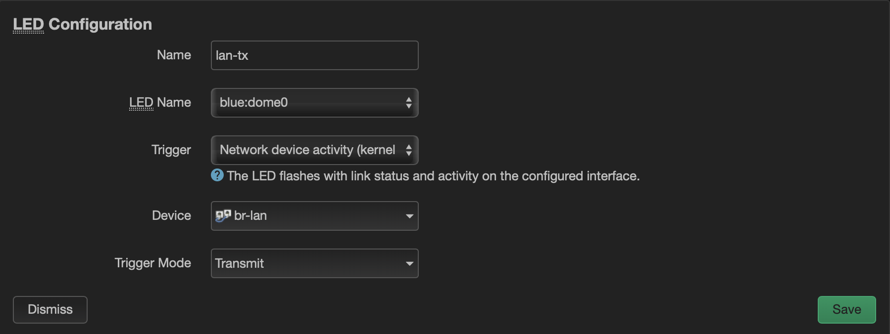 WPN824 Dome LED Configuration
This process can be repeated for each of the 7 dome LEDs. So while it’s not specific to the antenna, if you have multiple networks (think Home, IoT, Guest, etc.), you can set up a trigger for activity on that interface.
 WPN824 Dome LEDs