
· 12 min read

DISCLAIMER: This post reflects myself and only myself in its entirety. It is in no way related to or sponsored by my employer or anyone else. On February 3, 2023, I had reached out to Hughes in attempt to properly disclose these findings. Over the course of 6 months, we were trying to find a way for both sides to do this safely. As of August 30, 2023, I have received no further responses from Hughes' security team. I've attempted to contact them 3 times since but have not gotten a response.

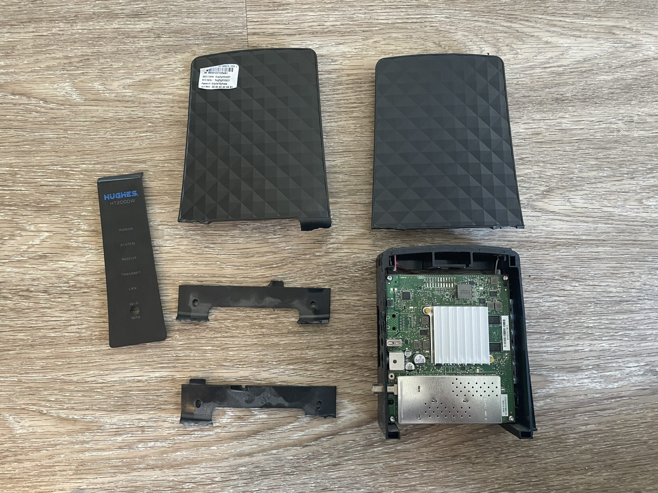
HughesNet is a USA-based satellite internet provider. As of writing, they are on their 5th generation of satellite technology and issue customers the HT2000W satellite modem as part of their "VSAT" package. For those who don't know, VSAT stands for "Very Small Aperture Terminal", which effectively means a "small", two-way antenna. This is a bit of a unique piece of hardware, given that it ties together a satellite modem and a wireless router into one package. Unfortunately, there's next to no information on this device outside of the FCCID docs, and the pictures are so blurry and useless. #challengeaccepted Before we get started, I should note that this firmware appears to be at least a couple years old, so their security posture may have changed significantly. Anyways, let's crack this bad boy open!

Spoiler: Opening the case has been the biggest challenge thus far.

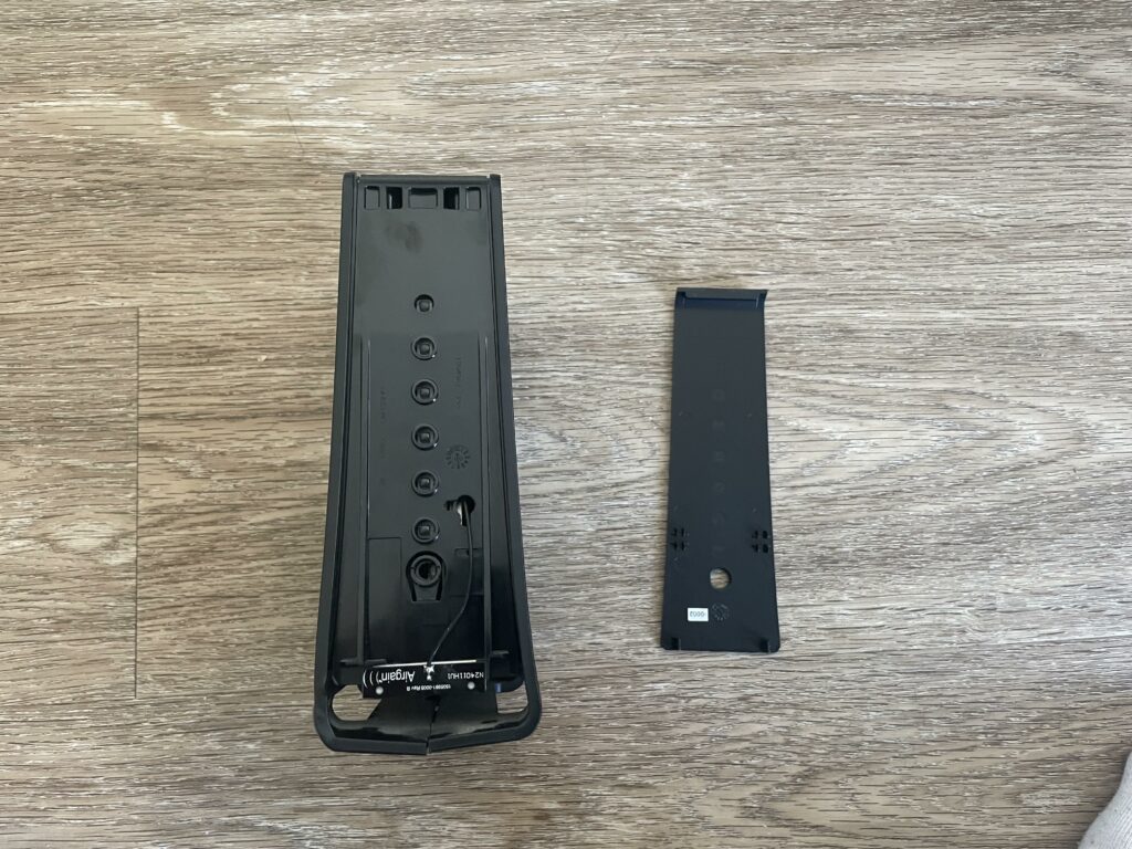
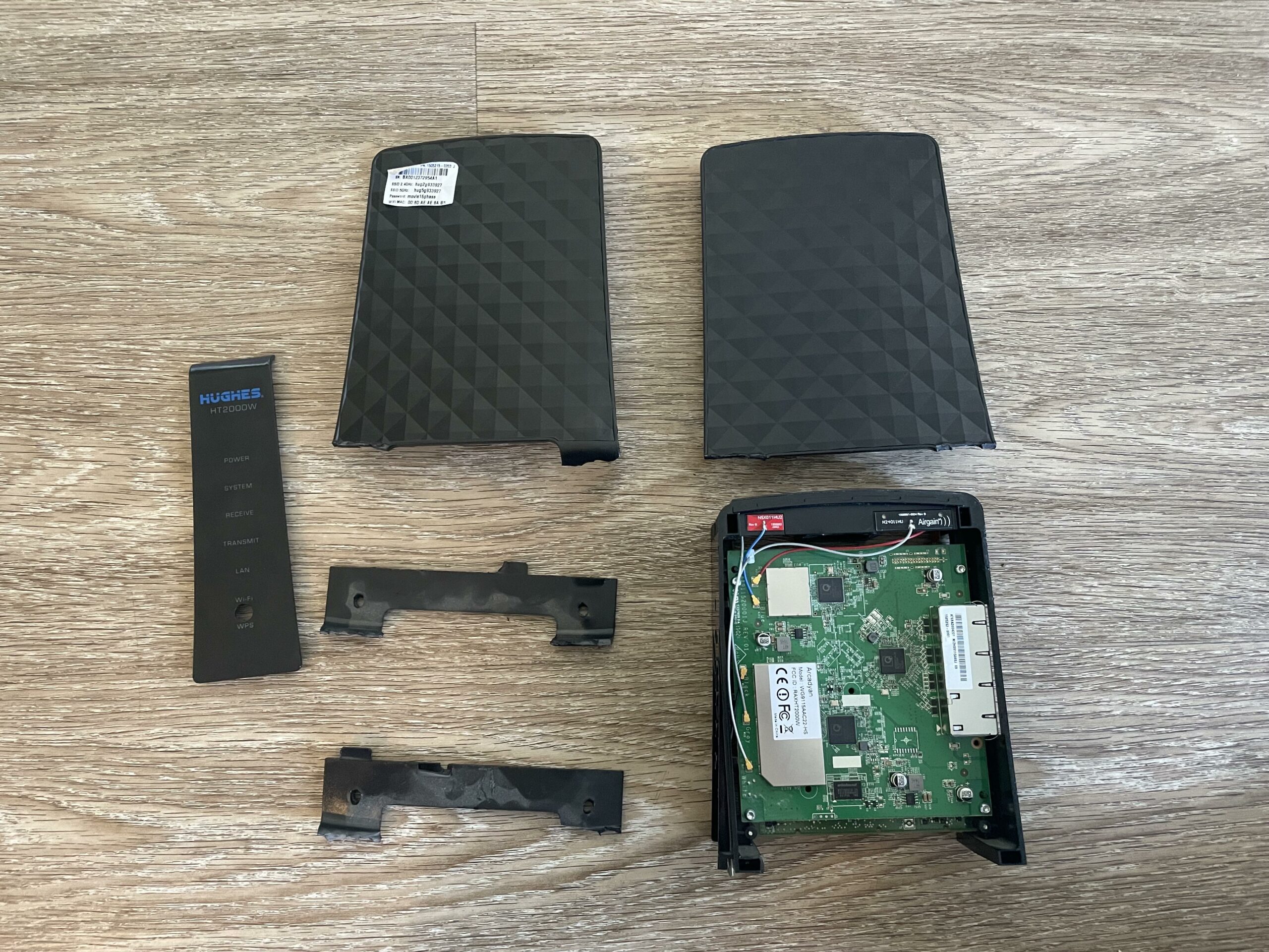
Let's start by taking off the front panel. This just pops off its little clips, easy. You'll find a 5GHz Airgain antenna attached to the front of the modem, followed by 4 more spread throughout the chassis. There are 3 5GHz antenna and 2 2.4GHz antenna. Presumably, this would be a class AC1600 router, however the 5GHz radio only supports 2 spatial streams, making this really a class AC1200 router.

front-panel

Now, it would appear that whoever services these modems has a special tool as getting the rest apart was insanely annoying. Let's start from the bottom. I ended up breaking off the feet to get to the little clips.

bottom-feetbroken-bottom-footbottom-clips-removed

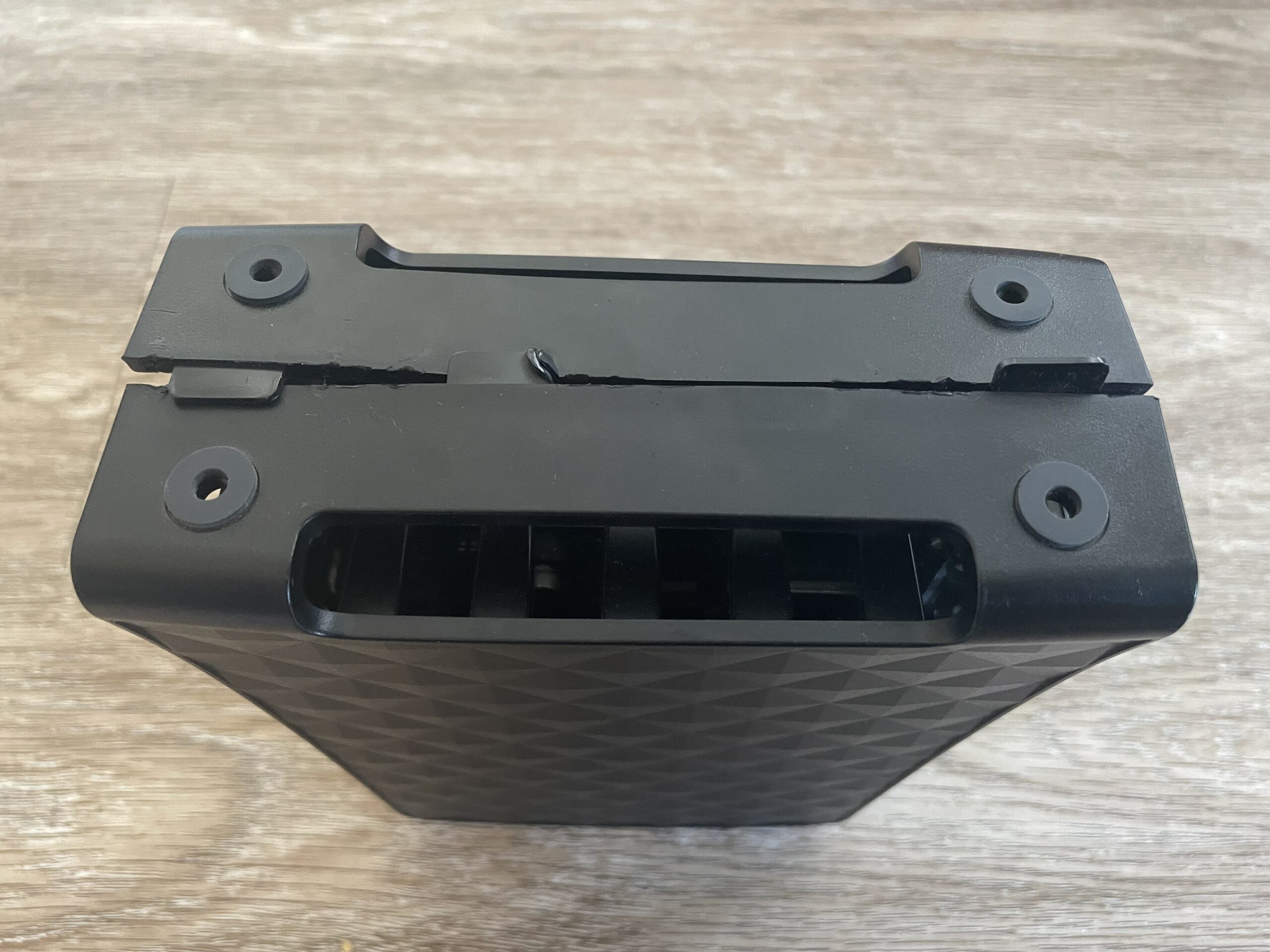
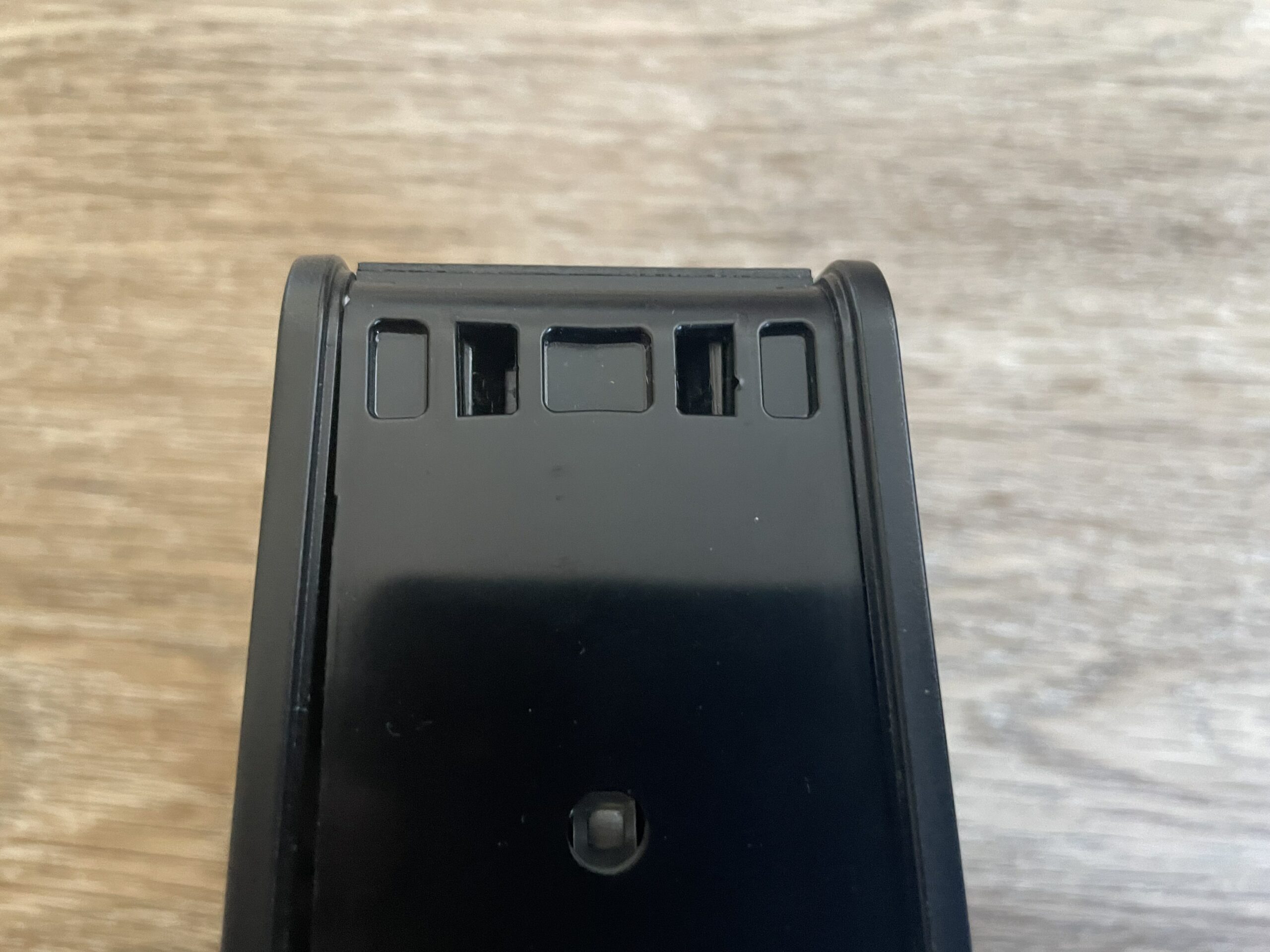
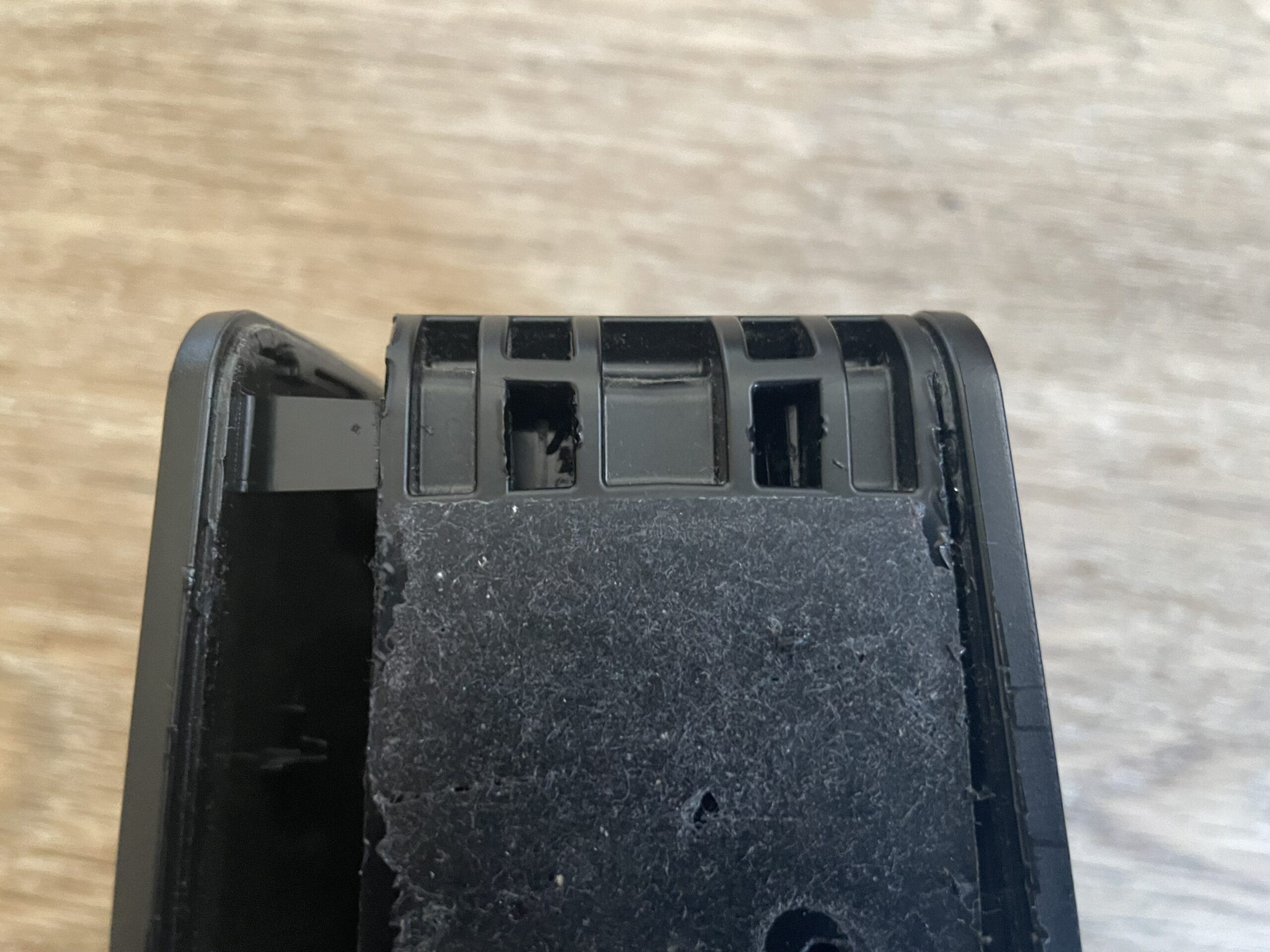
Directly below each of those 4 circles are little clips. They're really difficult to push in and unlock the side of the case, so I basically ended up just breaking the clips with a flathead screwdriver. I did say this was the hard part!

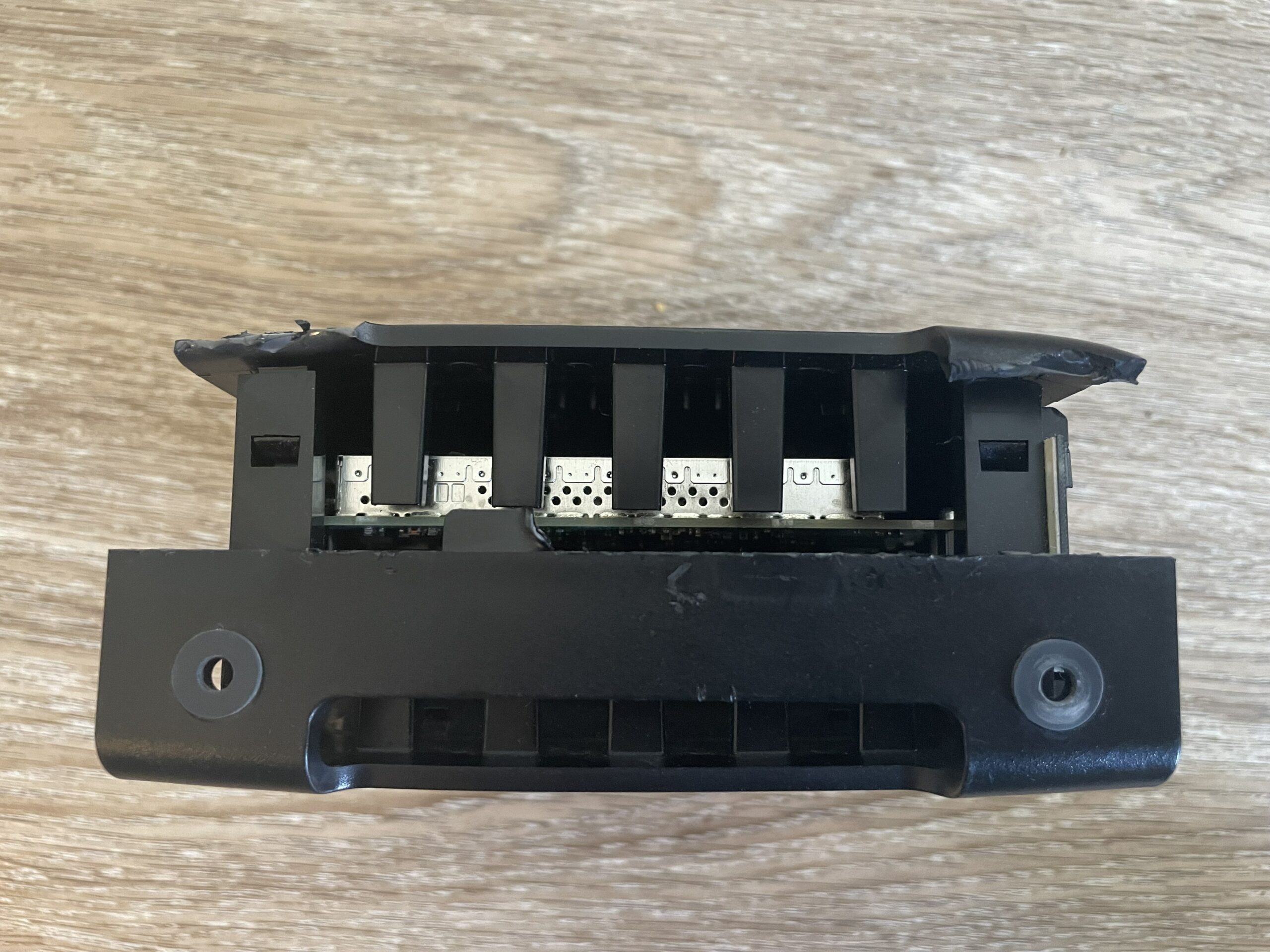
On the front and the back of the top part of the modem, there are 4 more of the same clips. Again, I pushed this with a flathead screwdriver until it opened.

top-clips-fronttop-clips-back

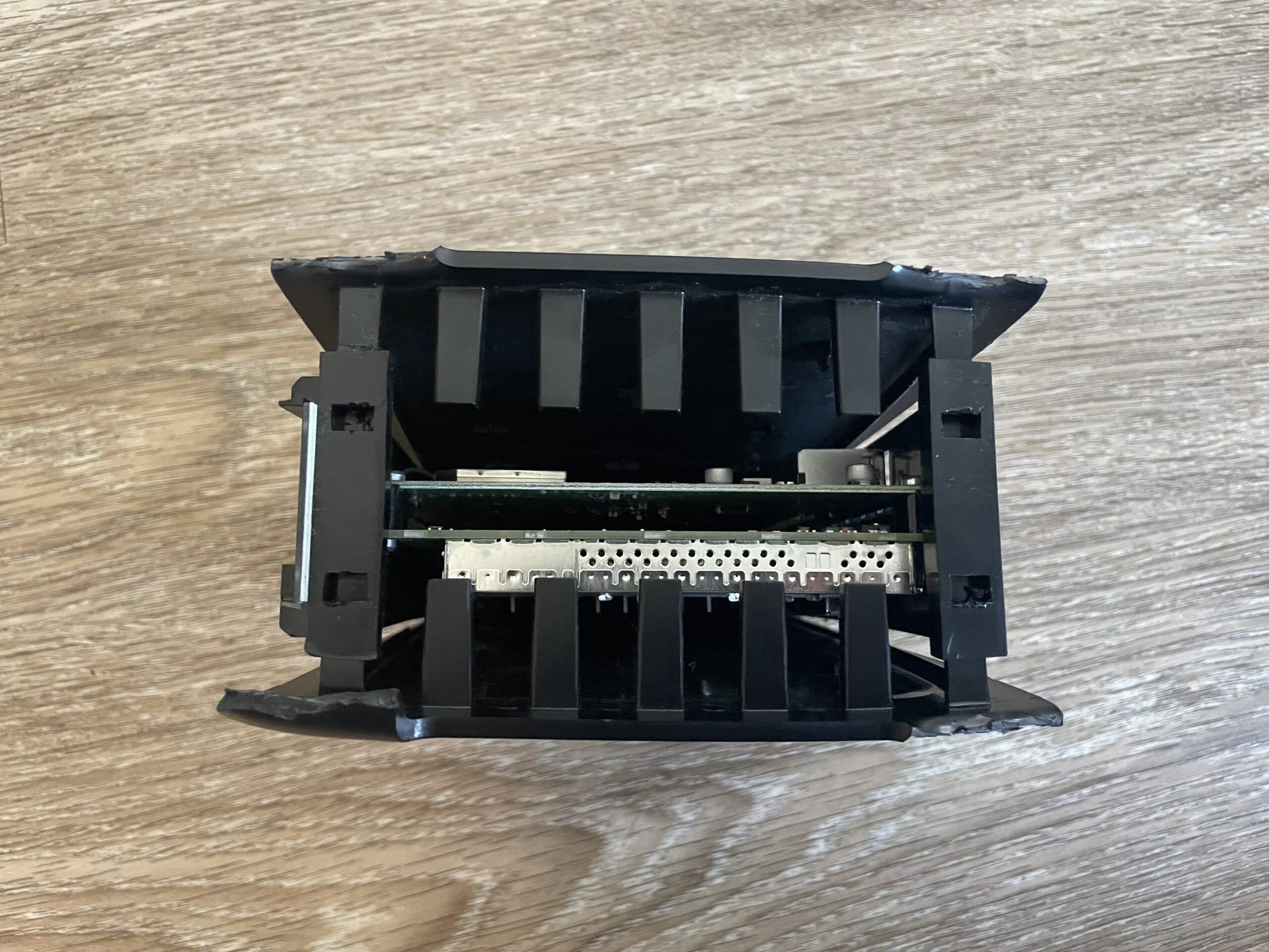
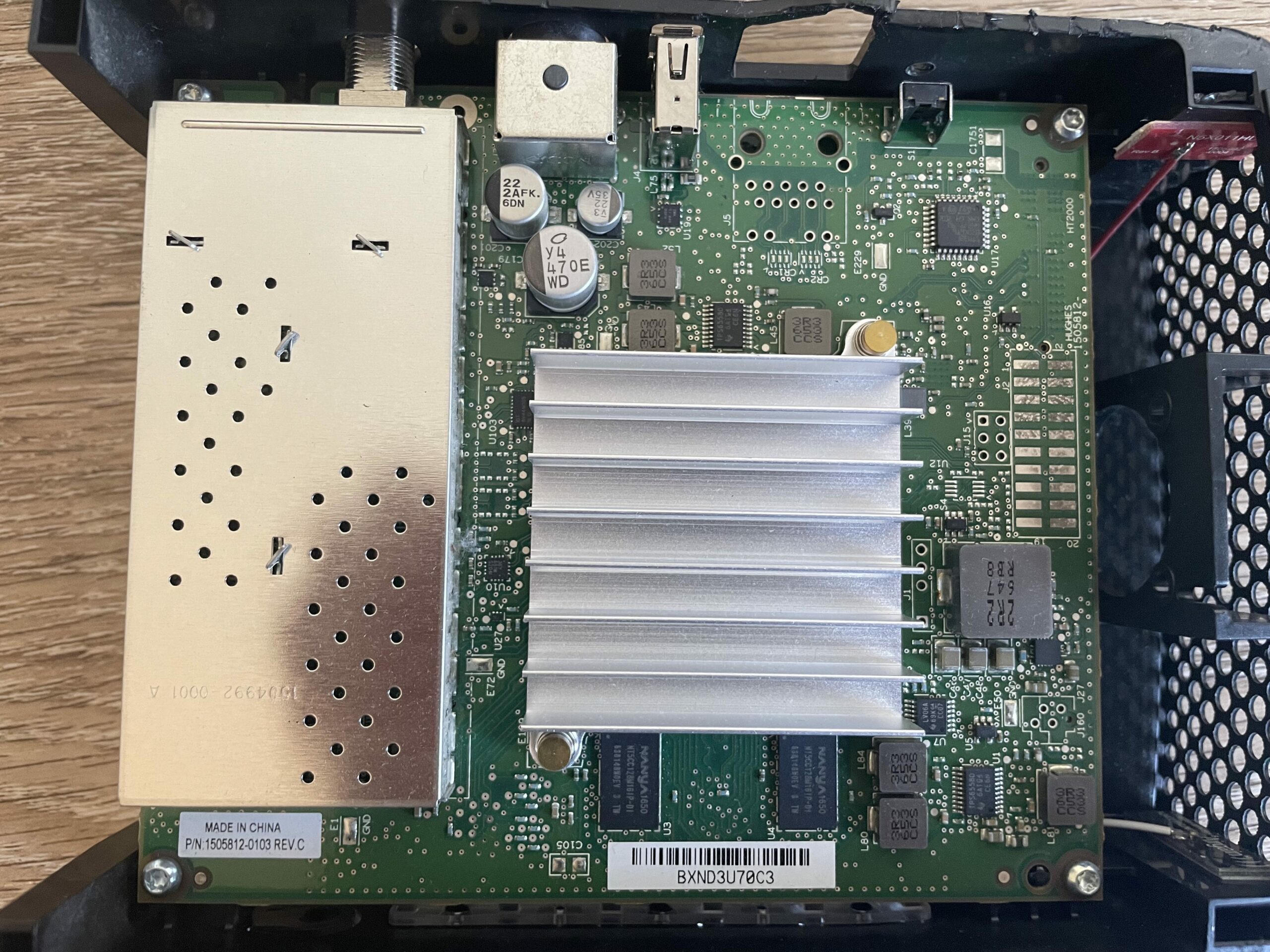
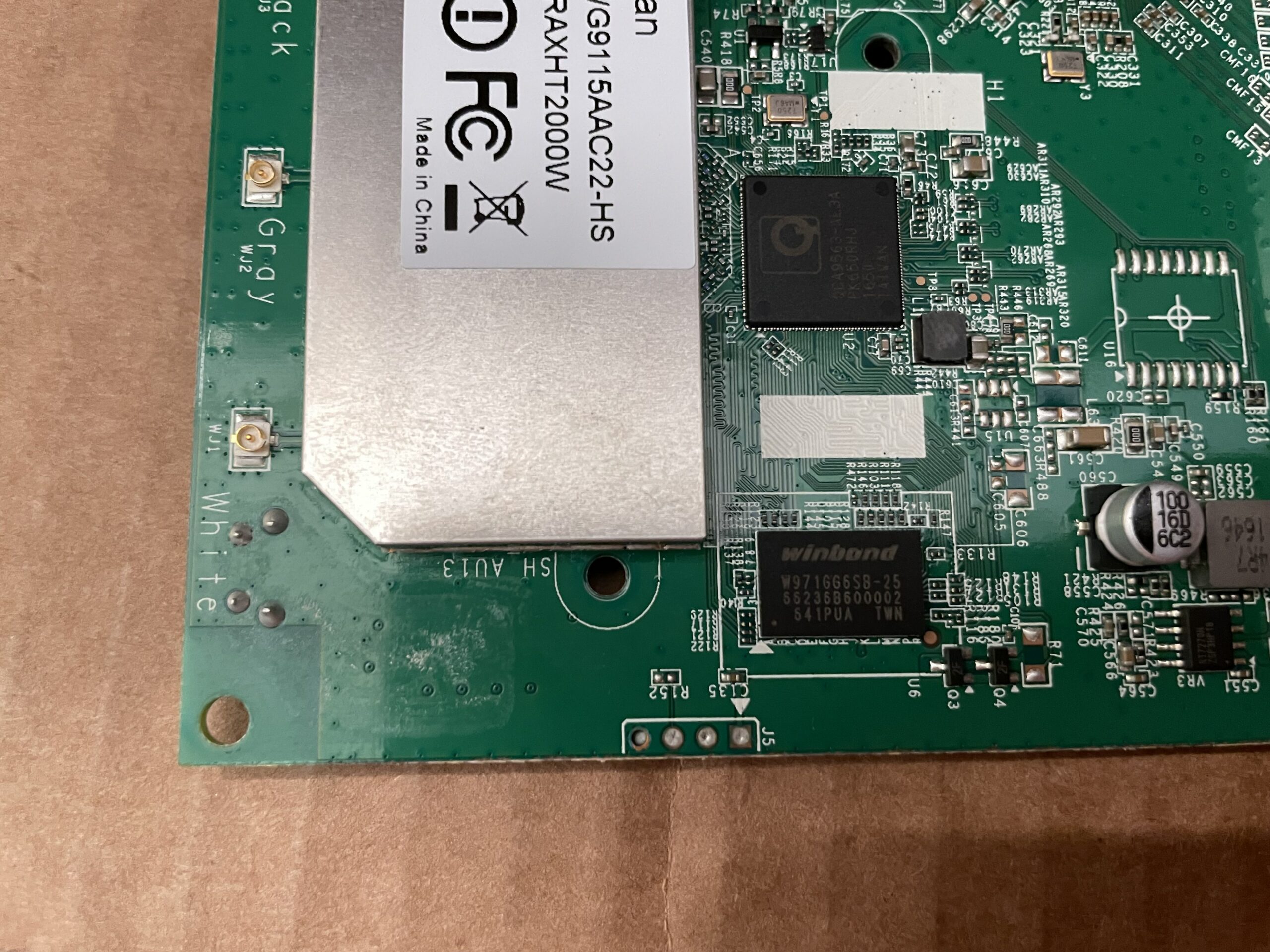
A "cool" feature of this modem is it is actually 2 physical PCBs connected together with something I'm unfamiliar with. Here's an FCC doc showing the pinout of this connector. The modem PCB is identifiable by the coax connector and the big heat sink on the FPGA. This is where all the signal processing happens.

On the back side is the router PCB which is identifiable by the ethernet ports, 3 Atheros chips and 2 RF shields.

router-pcbmodem-pcb

Here's some close-ups.

router-close-upmodem-close-up

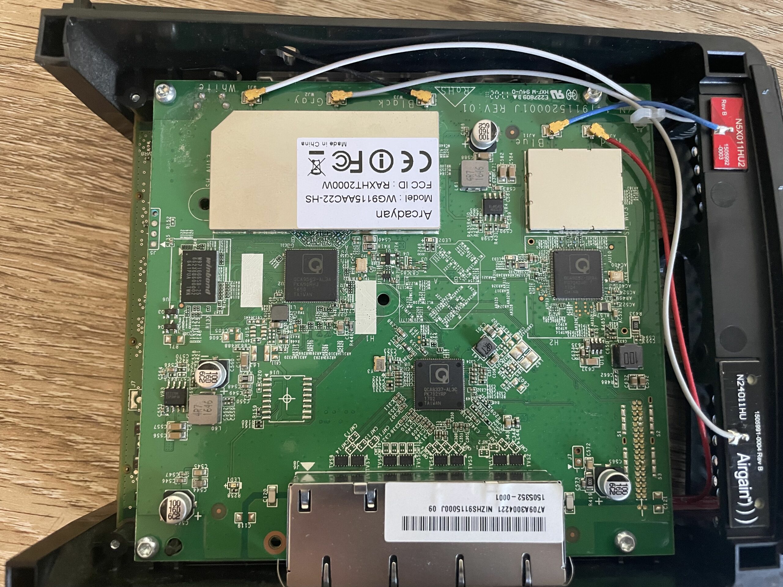
There's 4 screws on the corners on both the modem and router PCBs holding them to the chassis. Taking off the 4 on the router PCB allows us to expose the back sides of both boards. We'll start with the router board.

router-flash

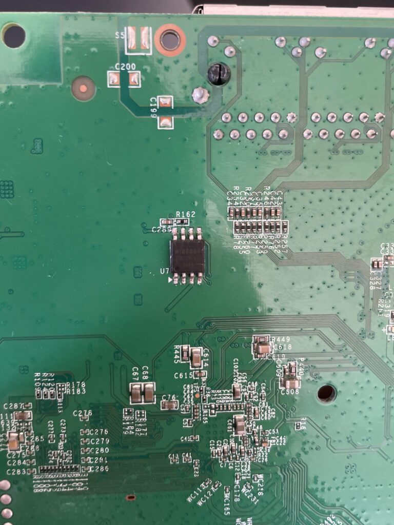
The only thing of interest is the Winbond 25Q128FV serial NOR flash. I did attempt using a SOIC-8 chip clip and my Shikra board to dump the flash, but flashrom had trouble identifying the chip. Initially, I had been using a Raspberry Pi 4 as a 3.3V source to power the chip. After hours of frustration and 0 bits dumped from the chip, I figured the 3.3V header on the pi wasn't supplying enough current. I also powered WP, which is Write Protect and basically makes the chip read-only, and the HOLD pin. Here's the schematic of the chip.

winbond-25q128fv

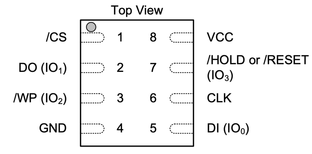
Next, I tried powering the chip with an external power supply, still with no success. Admittedly, I spent far too much time trying to get this to work and my best guess is that something else on the board is preventing me from reading it. In effort to not potentially brick the device by desoldering it, let's try something else.

You may have noticed on the router close-up image above 4 suspicious points below the RF shield. It's a shot in the dark, but let's solder some female jumper cables to them.

router-uart-headerrouter-uart-soldered

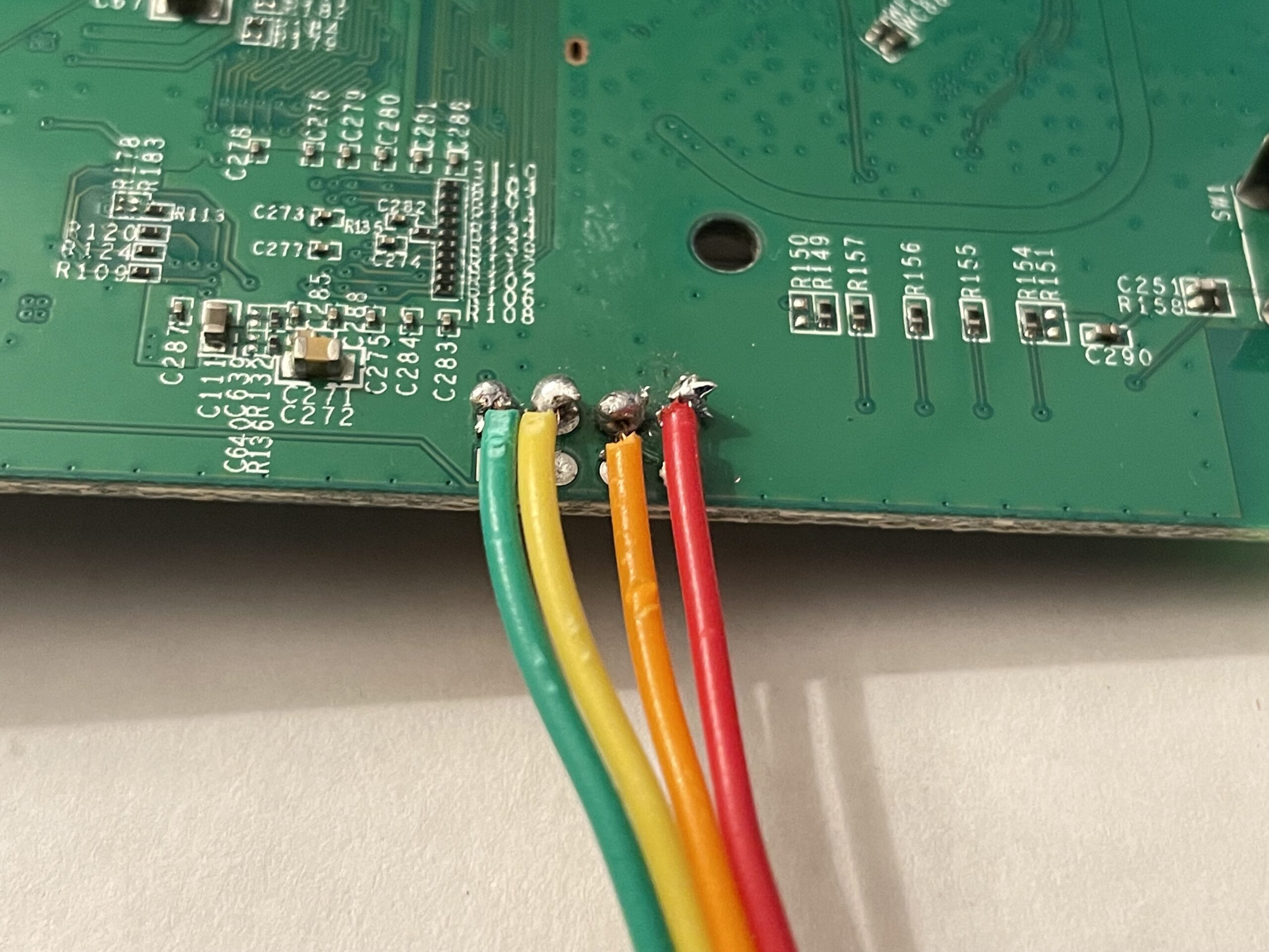
You probably guessed by the captions. Yep, this is UART! From the right picture, we will assume left is pin 0 and right is pin 3 (the left picture is inverted).

  • Pin 0: VCC
  • Pin 1: TX
  • Pin 2: RX
  • Pin 3: Ground

Booting Up

Here's a paste of the bootlog which I highly recommend checking out.

Looks like the router has U-Boot (surprise!) and runs some variant of OpenWrt. It's likely based on Chaos Calmer based on the kernel version running. U-Boot also reports 10 mtd partitions:

[    0.480000] 0x000000000000-0x000000040000 : "ub"
[ 0.490000] 0x000000040000-0x000000050000 : "ub-env"
[ 0.490000] 0x000000050000-0x000000400000 : "tiny"
[ 0.500000] 0x000000400000-0x000000510000 : "knl-1"
[ 0.510000] 0x000000510000-0x000000fb0000 : "root-1"
[ 0.510000] 0x000000fb0000-0x000000fc0000 : "board_data"
[ 0.520000] 0x000000fc0000-0x000000fd0000 : "seccfg"
[ 0.530000] 0x000000fd0000-0x000000fe0000 : "pricfg"
[ 0.530000] 0x000000fe0000-0x000000ff0000 : "dev"
[ 0.540000] 0x000000ff0000-0x000001000000 : "ART"

Here's what I'm interpreting them as:

  • U-Boot
  • U-Boot Environment
  • Unknown
  • Kernel Image
  • RootFS
  • Board configuration data (factory configs)
  • Security configurations - board config (contains /etc/config/.glbcfg)
  • Private config - more board config? (contains /etc/config.glbcfg)
  • Dev?
  • Radio calibration data

Once the router board finished booting, it drops us into an unprotected root shell!

/ # id
uid=0(root) gid=0(root)
/ # ls
bin etc overlay sbin tmp var
dev lib proc sys usr www

Let's see what else we can find at quick glance. Might be handy to check /etc/shadow to see if there are any hashes we can crack.

/ # cat /etc/shadow
root:$1$wqxmW461$MPspcLun.QAfCT2iDYcSm.:0:0:99999:7:::
daemon:*:0:0:99999:7:::
ftp:*:0:0:99999:7:::
network:*:0:0:99999:7:::
nobody:*:0:0:99999:7:::

Bingo! md5crypt (hashcat mode 500). Before we take a swing at that hash, let's see what else we can find. Inside /etc there's a script that looks to configure telnet which makes use of a built-in management tool dubbed mng_cli. It runs the command mng_cli get ARC_SYS_ADMIN_Password. Let's run it ourselves and see what happens.

/ # mng_cli get ARC_SYS_ADMIN_Password
yan2kwhes!

Okay cool, looks like a password. I wonder... router-root-hash-crack

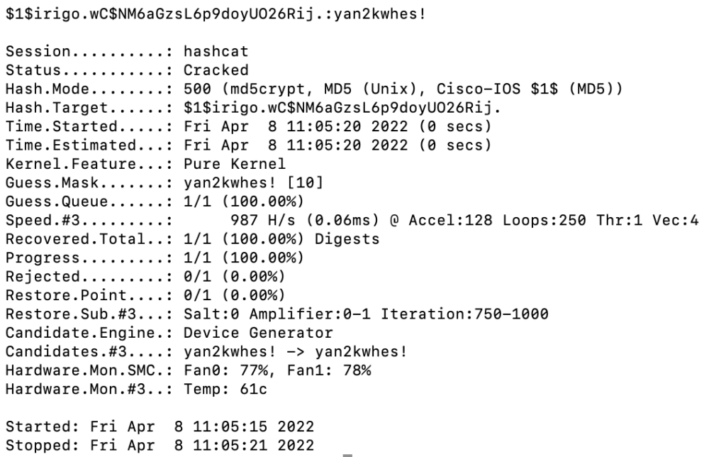
Yep, root password is yan2kwhes!

The Modem

Alright, that's all cool and dandy, but I want to poke at the modem side of things now. Another look at the PCB shows another provocative header just above the heatsink.

modem-uart

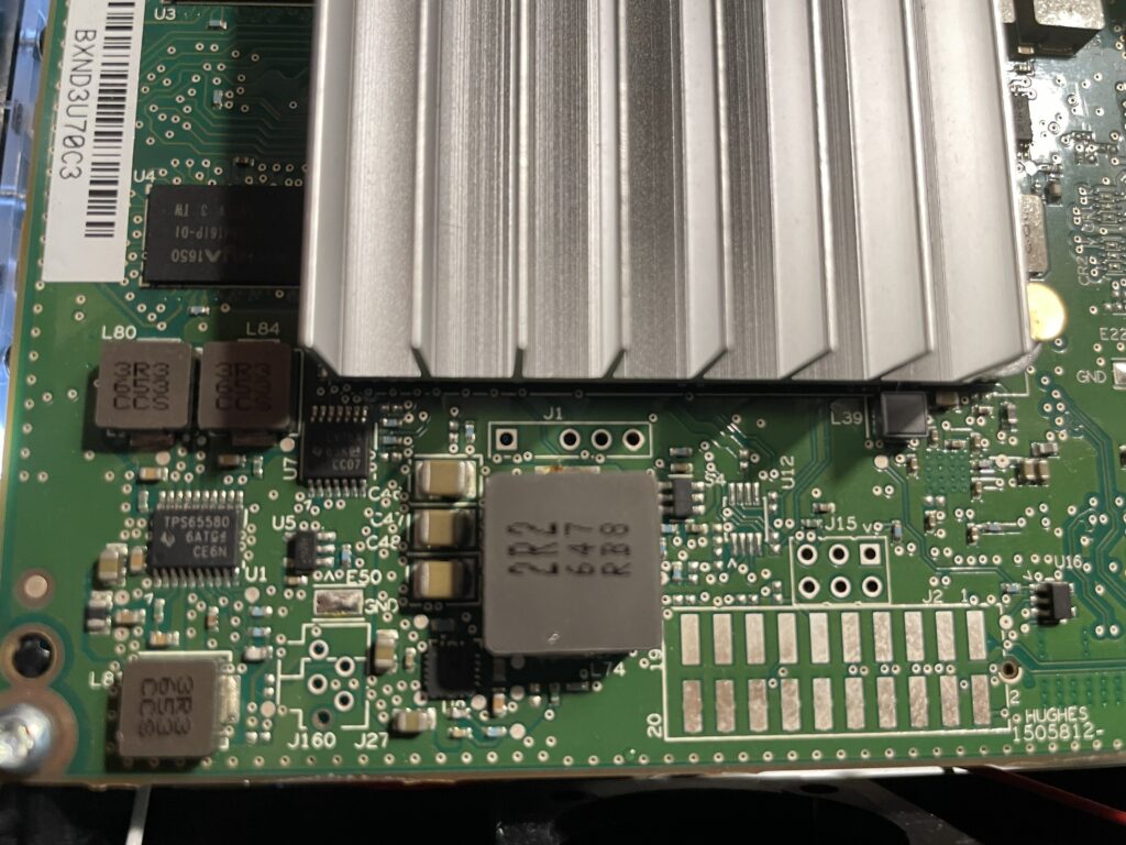
Spoiler alert: it's another UART connector! From this picture, we assume the left pin is 0 and the right pin is 3.

  • Pin 0: VCC
  • Pin 1: TX
  • Pin 2: RX
  • Pin 3: GND

Here's the bootlog, which I also highly recommend you open.

thebe-moon

Interestingly, HughesNet's most recent fleet of satellites are named Jupiter, like the planet. Thebe is one of four inner moons, and is the second largest.

SPOILER: There's an interesting reference in /cm_data/jupsw/terminal/, the directories thebe, callisto and ganymede are present. Several other scripts reference Ganymede and Callisto, which are the first and second largest moons, respectively. A comment in /vsat/etc/setup.sh says

# 06/22/15  O'Neil      move build-time fakeroot stuff to here                         
# where it is not fake
# BTW, this is now Thebe, not Callisto.

So, it looks like Callisto has been rebranded into what is now Thebe. If I had to guess, the HT2000L (MultiPath variant) or the HT2000 (no wireless capabilities) is Ganymede, but I don't know for sure.

Anyways, once the boot process is complete, we aren't dropped into a root shell and the root credentials we found on the router are not working here. After guessing a few possible combinations, I decided I'd be better off exploring other options. Let's reboot the device and see if we can drop into a U-Boot console.

modem-u-boot

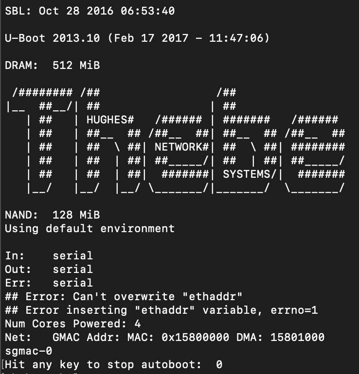
Boom! The modem has a "stop autoboot" countdown, which means we can interrupt the boot process and access the bootloader console. Mkay, now what? U-Boot is very limited in what it can do so we might be a bit stuck here. We can see that there's a kernel image uImage on here.

modem-images

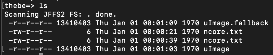
This probably has a user account and hash we can try to crack, but how could we get this off the device? There's no tftp and the ethernet ports aren't connected to the modem anyways, they're on the router so that's out of the question. Insert md, aka memory display. md is a tool built into U-Boot that allows you to print to the console starting from an address up to a number of bytes. Also cool, but we don't know where this kernel image is located in memory. A look at the bootlog shows that right after the autoboot timeout, the kernel is loaded in at address 0x80800000 and it is 13410403 bytes (hex 0xCCA063).

### JFFS2 loading 'ncore.txt' to 0x80800000
Scanning JFFS2 FS: .  done.
### JFFS2 load complete: 6 bytes loaded to 0x80800000
I'm OK
### JFFS2 loading 'uImage' to 0x80800000
### JFFS2 load complete: 13410403 bytes loaded to 0x80800000
## Booting kernel from Legacy Image at 80800000 ...
Image Name: Linux-3.10.53.cge-rt50
Image Type: ARM Linux Kernel Image (uncompressed)
Data Size: 13410305 Bytes = 12.8 MiB
Load Address: 80008000
Entry Point: 80008000
Loading Kernel Image ... OK

So U-Boot knows how to load this into RAM at a particular address, let's do the same. printenv shows us U-Boot environment (for our purpose, boot config) and there's a handful of useful information.

modem-uboot-env

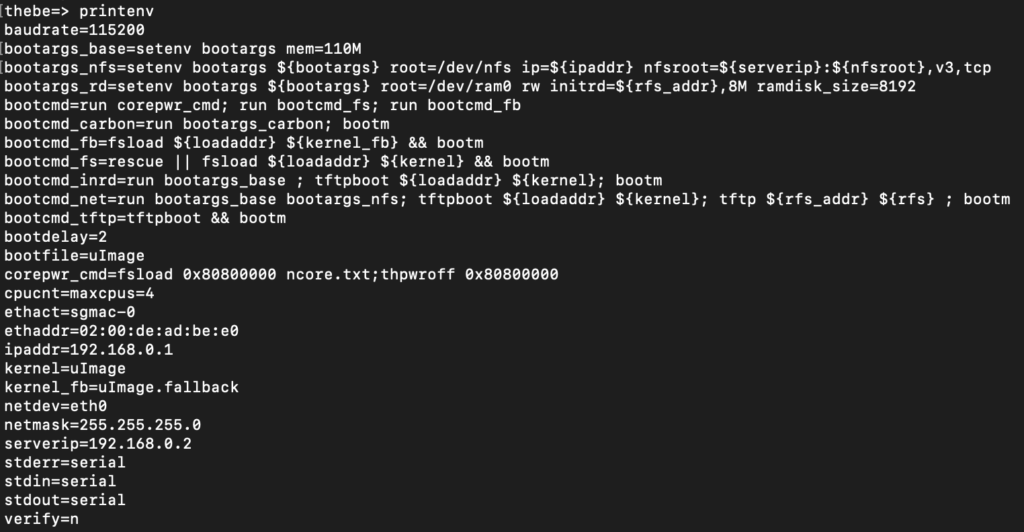
bootcmd is what runs under the hood to boot up the device.

bootcmd=run corepwr_cmd; run bootemd_fs; run bootemd_fb

So it runs corepwr_cmd first, which appears to load ncore.txt to 0x80800000. I'm honestly not sure that this is even necessary, but let's run it to ensure we follow the same boot process that the modem does: run corepwr_cmd on the console. The next step bootcmd takes is it runs bootcmd_fs, which loads the kernel into RAM. Looks like what we need! BUT - bootm is going to boot the device, which we don't want right now. So let's just run fsload ${loadaddr} ${kernel} by hand. We can assume that ${loadaddr} is 0x80800000 based on what the bootlog reports and ${kernel} points to uImage.

modem-load-kernel

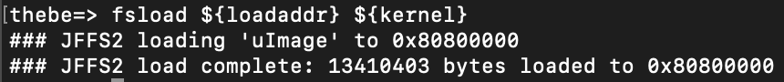
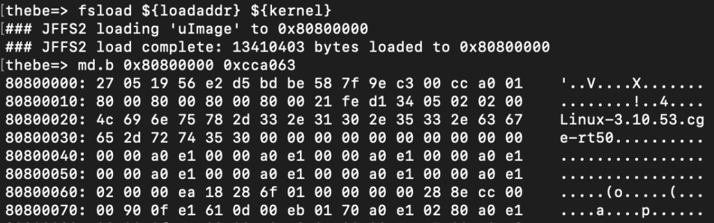
Success! Now we know that this kernel image is going to be at 0x80800000 and is exactly 0xCCA063 bytes. I'm using Minicom so let's configure it to write out everything to a file. Since the kernel image (root filesystem) is now in RAM, we can dump it using md. On Linux, press your host key + L (usually ctrl or option on macOS) and set Minicom to write out to a file. I named mine uImage.cap. Now we can start dumping the kernel with md.b 0x80800000 0xCCA063. This will start reading from 0x80800000 for 0xCCA063 bytes, again, the size of the kernel image. It will probably take a couple hours as serial is quite slow. The .b tells memory dump to dump in binary.

You'll know its working properly if you see something related to the kernel while the memory is dumping.

modem-dump-kernel

When the dump finally completes, open up your cap file in a text editor and remove any leading lines and whitespaces before the first 0x8080000 line. If the last line appears to be cut short, pad it with 00 to match the length of the former line, and then pad the far right column with .s. We can then use uboot-mdb-dump to convert this text file to a raw binary: python3 uboot-mdb-to-image.py < uImage.cap > uImage.bin.

Awesome, now we have a binary of the kernel image! Let's open in with Binwalk: binwalk -eM uImage.bin There's a few compressed archives recursively extracted, and we found the rootfs!

alamarche@dev:~/cpio-root$ ls
bin boot dev etc fl0 home init ip6tables iptables lib linuxrc media mnt mypc proc pstore root sbin sys tmp usr var

Using our linux knowledge, we know that /etc/shadow should have a hash for any user accounts.

alamarche@dev:~/cpio-root$ sudo cat etc/shadow 
root:yJmLbLQDH1A7A:17022:0:99999:7:::
daemon:*:0:0:99999:7:::
ftp:*:0:0:99999:7:::
network:*:0:0:99999:7:::
nobody:*:0:0:99999:7:::
thebe:BKMVXGc0xaUWM:17022:0:99999:7:::

2 accounts, root and the wonderful thebe! These are descrypt hashes and boy do they have a wonderful flaw. Every descrypt hash is truncated to 8 bytes (8 characters) so at most, our hashcat mask will be ?a?a?a?a?a?a?a?a. This is pretty feasible on modern hardware, and I'm lucky enough to have an RTX 3080 and an RTX 3080 Ti at my disposal. I was able to crack them both in under an hour

root:yJmLbLQDH1A7A:17022:0:99999:7::::bp2skztm
thebe:BKMVXGc0xaUWM:17022:0:9999:7::::thac@gth

Let's reboot the modem now and try to log in.

thebe:/root# whoami
root

Interestingly, iptables don't appear to be used here and I haven't found a compensating firewall (yet).

Getting SSH

Looking at /vsat/etc/setup.sh again highlights these lines:

if [ -f /fl0/englab.dat ] ; then                      
/fl0/apps/sshconfig.sh 0.0.0.0 enableroot 0
fi

Apparently, if /fl0/englab.dat exists, SSH is enabled and listening on all interfaces (even WAN???). So, lets create that file and reboot.

# touch /fl0/englab.dat
# reboot -f

Remembering that the modem is at 192.168.0.1, let's connect and try to SSH to that IP. SSH is open!... but the keys don't work. Let's take another dump via U-Boot and see what's going on.

root:JPji6SfLPRjRs:17022:0:99999:7:::
daemon:*:0:0:99999:7:::
ftp:*:0:0:99999:7:::
network:*:0:0:99999:7:::
nobody:*:0:0:99999:7:::
thebe:BKMVXGc0xaUWM:17022:0:99999:7:::

New hashes, still descrypt. Let's crack them!

root:supernova
thebe:thac@gth

Boom, SSH! So it appears that the modem is now in some kind of "Engineering Lab" mode. This should make things a little easier. FWIW, SSH from the modem to the router does work using the root account and the password we found earlier.

· 6 min read

As always, use the resources provided here responsibly. I am in no way, shape or form responsible for what you do with this.

DOCSIS is the Data Over Cable Service Interface Specification, which is the technology that runs on cable modems in North America. EuroDOCSIS is largely the same, with some small tweaks to make it operate in European markets. This post shares some ideas and concepts that are common for many cable devices using the Puma chips. It will also focus more on the RDK-B implementations.

There are a variety of different OSes that Puma modems run. Some are proprietary Linux flavors, e.g. the SB6190 https://sourceforge.net/projects/sb6190.arris/files/, others run a more unified OS called Reference Design Kit for Broadband. In my own opinion, RDK-B is an over-complex and extremely bloated OS that tries to do too much in overly complex ways.

An example is the Utopia software package. It tries to manage bridging, LAN services, DHCP, SSH, firewall, logging and more. On top of this, the firewall is managed behind the scenes by a C application (firewall.c) that more or less just applies iptables rules. I think everyone would consider this an anti-abstraction that makes it significantly more difficult to understand develop with. As a hacker though, it presents much more attack surface! Not to mention, the utopia "bundle" should really be broken out into init scripts/service files and their associating config scripts. Further, there are many CLI tools: dmcli, syscfg, sys event, etc. that make operating the OS a disaster. On top of all this, a database is used to store some parts of the config, rather than placing them all somewhere actually organized and useful (see OpenWrt's UCI where everything goes into /etc/config).

Overall, the unification goal of RDK-B seems to do the opposite, at least all of the modems I've looked at the run RDK-B are twisted and obscured so far that they barely resemble it any more. Enough bashing though, let's continue!

Chip Architecture

The Puma 6 and Puma 7 chips are nearly identical from the user's perspective; the only difference being that Puma 6 only supports DOCSIS 3.0 while Puma 7 supports DOCSIS 3.1. The upcoming Puma 8 chip will support DOCSIS 4.0, but its design is currently unknown as it is not available to the public yet.

Both Puma 6 and 7 use a dual core design, where one core is an armv6eb (big endian) core and the other is an Intel i686 32-bit core. Neither of which are super powerful, but they do their job okay-ish.

Basic Chip Security

In proper implementations, the CPU will be "fused", meaning a public key is stored inside the CPU's eFuses. These are tiny OTP (One-Time Programmable) memory fuses, and they serve the purpose of being tamper resistant; once they are written to, they cannot be changed. At a really high level, the idea is that each firmware component (bootloader, kernel, etc.) are signed with the corresponding private key by the device manufacturer. A cryptographic check is performed on these signed images using the public key stored in the eFuses. This way, (assuming no bootROM exploits exists or they didn't leave UART open), it can be pretty safely assumed that the code running on the device is the original code intended to be run by the manufacturer. For a more in-depth overview, check out Mediatek�' Wiki on it. This is great, however when manufacturers want to be the first to push a new product to the market, sometimes these security features are "forgotten".

DOCSIS Core: armv6eb

The DOCSIS core is, by today's standards, ancient. Nobody uses big endian ARM cores (granted the justification is that this matches network byte order), and armv6 itself is probably considered antique by now. That being said, its main goal is to run and control any DOCSIS protocol or signal processing code.

# uname -a
Linux puma 4.9.215 #1 PREEMPT Tue Apr 7 14:02:36 UTC 2020 armv6b GNU/Linux

Router-Gateway (RG) Core: i686

The router-gateway code is also ancient by today's standards. Nobody uses 32-bit Intel cores any more. That being said, its main goal is only really useful in gateway devices that is, cable modems advertised with built in wireless routers. On standalone cable modems, this core is largely unused. However, gateway devices often use it to serve as the customer's wireless router, firewall, etc. In this configuration, this core is what gets a public IP address from the ISP and then shares it to the customer via Network Address Translation (NAT).

Stitching Them Together

There are a few different communication mechanisms that take place between these cores, but most notably is the creation of the adp0 and ndp0 interfaces that connect the two. Commonly, vlan 555 bridges the two CPUs.

armv6eb core: 192.168.254.253, network device processor (ndp0)

3: ndp0.555@ndp0: <BROADCAST,MULTICAST,UP,LOWER_UP> mtu 2000 qdisc noqueue state UP group default qlen 1000
link/ether 00:50:f1:00:00:00 brd ff:ff:ff:ff:ff:ff
inet 192.168.254.253/24 brd 192.168.254.255 scope global ndp0.555
valid_lft forever preferred_lft forever

i686 core: 192.168.254.254, appication device processor (adp0)

    link/ether 00:50:f1:80:00:00 brd ff:ff:ff:ff:ff:ff
inet 192.168.254.254/24 brd 192.168.254.255 scope global adp0.555
valid_lft forever preferred_lft forever

I want to run

Toolchains do exist to build software to run directly on these modems, but they are almost antique. Most need Ubuntu 12 to run. A different solution is to use musl-libc and build statically linked applications for one-off tools. For this, I created the Ubiquity Toolkit (blog post, GitHub). While statically linking can be a bit more painful as all the dependent libraries need to be built as well and linked to by hand, I've found it much more rewarding to figure it out once for one arch, then just switch the cross compiler to build it for another. I'd recommend you read the blog post and check out my GitHub to see how you might build another software package to run on these devices! Pull requests are always welcome.

Keys, Please!

In many cases, SSH is enabled between the two via a dropbear private key, often located in /root/.ssh/id_rsa on each core's rootfs. While this works when your ssh binary is from dropbear, it won't work when you're using OpenSSH. However, dropbear includes a handy binary that allows easy converting between the two. To go from dropbear to OpenSSH and put the new key at /tmp/ida_rsa:

dropbearconvert dropbear openssh /home/root/.ssh/id_rsa /tmp/id_rsa

If SSH is not open on the LAN, you can probably open it by inserting an iptables rule on the RG side:

iptables -I INPUT -p tcp --dport 22 -j ACCEPT

Then use ssh on your local machine to remote in:

ssh -oPubkeyAcceptedKeyTypes=+ssh-rsa -oHostKeyAlgorithms=+ssh-rsa -I id_rsa root@<ip>

Otherwise, to pivot between cores, just use the included ssh binary and pass in the key and the RG or arm core IP.

· 4 min read

As always, use the resources provided here responsibly. I am in no way, shape or form responsible for what you do with this.

Having hacked/rooted many embedded devices, I've found a gaping hole in my tool belt; it's near impossible to find and "hacker" tools that can run directly on these devices. Most of these run on outdated kernels, with glibs or uclibc from 2013 or earlier and had firmware created using some proprietary toolchain/SDK that will only run on Ubuntu 2012 (hint Arris/Commscope/Vantiva). It was a huge pain and when I needed to launch an nmap scan directly from a satellite modem, I couldn't! That's why I created the Ubiquity Toolkit.

Source: https://github.com/soxrok2212/ubiquity-toolkit

The toolkit consists of many super useful tools that have been fully statically linked. I put emphasis on fully. To ship a binary and have it run on any linux system, we must include the application's compiled code and also any supporting libraries all together. Otherwise, it may try to load a shared library from the running system which may not exist, or may not be compatible. This is achieved by using musl-libc over the standard glibc.

For a more in-depth answer, check out this Stack Overflow link. Otherwise, the tl;dr answer is glibc makes extensive use of dlopen(), which loads a shared library. This defeats the purpose of statically linking, since we want EVERYTHING to be included in the binary. musl does not have these same limitations.

Rich Felker, the author and maintainer of musl-libc, also provides an awesome and easy to use repository to build musl cross compilers called musl-cross-make. For example, if I wanted to build an arm big endian cross compiler, I can just run:

git clone https://github.com/richfelker/musl-cross-make
cd musl-cross-make
make -j $(nproc) TARGET=armeb-linux-musleabi install

Just add output/bin to your path and you can call the compiler directly.

MIPS? ARM big endian? Who uses these any more?

Many communications devices use big endian and network byte order is also big endian. Network byte order is the widely agreed upon byte order for network traffic to be in. By having the communications device also be big endian, there is no need to waste CPU cycles switching data from big to little endian.

As an example, MaxLinear, maker of the Puma 7 DOCSIS chips, who previously purchased Intel's Puma 6 intellectual property, who previously purchased this formerly Puma 5 IP from Texas Instruments, uses a dual-cpu design, where the networking processor is an armv6 big endian core. Thus, the armeb-linux-musleabi toolchain creates binaries that can run directly on cable modems.

So what exactly makes up the Ubiquity Toolkit?

In its repository form, the Ubiquity Toolkit is just a collection of Makefiles that take care of downloading a tools and support libraries, configuring them, applying necessary patches, and then building them, while linking to any necessary libraries. The output is a fully statically linked and stripped down binary (for size) that should run on any linux system.

Pre-compiled versions are available here: https://cantcrack.me/binaries/ but don't expect them to be updated very frequently as stuff breaks with each version and it's a massive pain to figure out what each time.

Here's a quick look at the Busybox directory:

busybox-arm32:   ELF 32-bit LSB executable, ARM, EABI5 version 1 (SYSV), statically linked, stripped
busybox-arm32eb: ELF 32-bit MSB executable, ARM, EABI5 version 1 (SYSV), statically linked, stripped
busybox-arm64: ELF 64-bit LSB executable, ARM aarch64, version 1 (SYSV), statically linked, stripped
busybox-mips32: ELF 32-bit MSB executable, MIPS, MIPS-I version 1 (SYSV), statically linked, stripped
busybox-mips64: ELF 64-bit MSB executable, MIPS, MIPS-III version 1 (SYSV), statically linked, stripped
busybox-x64: ELF 64-bit LSB executable, x86-64, version 1 (SYSV), statically linked, stripped
busybox-x86: ELF 32-bit LSB executable, Intel 80386, version 1 (SYSV), statically linked, stripped

· 7 min read

You're probably here because you've come across the need to pass through multiple GPUs to one or more LXC containers on your Proxmox node. Maybe you have a media server that uses a GPU for hardware transcoding, an AI compute node, or, like me, a Hashcat cluster that utilizes GPUs for high-speed password cracking.

Whatever your need, LXC containers are so freakin' awesome. Not only are they super lightweight, but they provide great granularity over how you distribute your hardware. Oh, and not to mention, you can also pass in a GPU to more than one container, privileged or unprivileged (mind you, performance will be shared between the two; you don't just magically get more GPU power).

I should note that my journey started with Ben Passmore’s post over on his site, and this guide uses a lot of what he found to work as well. Anyways, here's what you need, and what I''ll assume you already have set up.

  • Proxmox 7 Host
  • 2 or more GPUs (I use an Nvidia GTX 980 and a GTX 1080)
  • One or more LXC containers (I used Ubuntu 20.04)

The official Nvidia docs for installing the drivers can be found here. I'll give a quick rundown of how this should work. We're going to add Nvidia's repository on both the host and the container so that we hopefully get matching driver versions, regardless of what's available from the package manager for our distro.

First, SSH into your Proxmox host and install a few packages. apt install pve-headers build-essential software-properties-common

Given that I require CUDA to do my work, I'll go ahead and add the CUDA repository. This should also install the traditional drivers as well.

add-apt-repository "deb https://developer.download.nvidia.com/compute/cuda/repos/debian11/x86_64/ /"
apt-key adv --fetch-keys https://developer.download.nvidia.com/compute/cuda/repos/debian11/x86_64/3bf863cc.pub
add-apt-repository contrib
apt update
apt -y install cuda

This will probably take a hot minute, so maybe grab a bowl of cereal or something. I like Fruity Pebbles.

When it finishes, let's create a udev rule so we can see our GPUs. Create the file /etc/udev/rules.d/70-nvidia.rules and fill it with the following:

# Create /nvidia0, /dev/nvidia1 … and /nvidiactl when nvidia module is loaded
KERNEL=="nvidia", RUN+="/bin/bash -c '/usr/bin/nvidia-smi -L && /bin/chmod 666 /dev/nvidia*'"
# Create the CUDA node when nvidia_uvm CUDA module is loaded
KERNEL=="nvidia_uvm", RUN+="/bin/bash -c '/usr/bin/nvidia-modprobe -c0 -u && /bin/chmod 0666 /dev/nvidia-uvm*'"

Now, when this is done, do a quick reboot and we should be able to see our GPUs with nvidia-smi. If not, you may need to load up the nvidia-uvm module into the kernel: sudo modprobe nvidia-uvm and try again.

nvidia-smi-1

Additionally, we should be able to see two cards at /dev/nvidia0 and /dev/nvidia1. Let’s make a note of the 5th column, 195 and 508. These are known as the cgroup values.

nvidia-cgroups

Further, since we're going to be transcoding, let's check /dev/dri for our rendering devices as well. Again, let's make a note of the 5th column, 226. Please note that these numbers will likely be different for your machine, and may change if/when a driver is updated. You may need to update your container configs after a driver update.

nvidia-dev-dri

One of the notable changes from Proxmox 6 to 7 that caused me a lot of head banging and maybe a few concussions is the move from cgroup to cgroup2. A cgroup, or control group, basically allows you to allocate resources, which is exactly what we need to do. Those numbers we wrote down are groups for our GPUs devices that we will need to pass through to our containers.

I've found it's generally safe to assume that column 6 is associated with /dev/nvidiaX or /dev/dri/cardX - aka if column 6 is a 1, then it'll be associated with /dev/nvidia1, etc. In my setup, I have 2 containers - one is my Hashcat node (container ID 101), and the other is my Jellyfin instance (container ID 109). Now, I've already briefly mentioned my requirements, but I'll reiterate here. I'd like to have both GPUs available to my Hashcat instance, but only my GTX 1080 available to Jellyfin, as Jellyfin can only use one GPU at a time.

Let's set up our Hashcat container first. Go ahead and open back up your SSH connection to your Proxmox node. Your LXC containers should be at /etc/pve/lxc/xxx.conf, where xxx is the container ID. We're going to add in a few lines to the bottom. Mine looks like this:

lxc.cgroup2.devices.allow: c 195:* rwm
lxc.cgroup2.devices.allow: c 508:* rwm
lxc.cgroup2.devices.allow: c 226:* rwm
lxc.mount.entry: /dev/nvidia0 dev/nvidia0 none bind,optional,create=file
lxc.mount.entry: /dev/nvidia1 dev/nvidia1 none bind,optional,create=file
lxc.mount.entry: /dev/nvidiactl dev/nvidiactl none bind,optional,create=file
lxc.mount.entry: /dev/nvidia-uvm dev/nvidia-uvm none bind,optional,create=file
lxc.mount.entry: /dev/nvidia-modeset dev/nvidia-modeset none bind,optional,create=file
lxc.mount.entry: /dev/nvidia-uvm-tools dev/nvidia-uvm-tools none bind,optional,create=file

The first 3 lines are allowing access to the cgroups we took down earlier. You can be more granular with your permissions and add a line for each file you want to give access, just change the * to the value in the 6th column from above. I'll have an example of this later.

The 4th and 5th lines allow access to both GPUs.

The remaining lines allow access to some cli and device control tools. Now, go ahead and restart the container.

Once it fires back up, we're going to follow almost the same install process to install the Nvidia drivers in our first container. Additionally, we are going to prioritize the Nvidia drivers over Ubuntu's included drivers. For Ubuntu 20, it�'ll look something like this:

sudo apt install build-essential software-properties-common
sudo apt-key adv --fetch-keys https://developer.download.nvidia.com/compute/cuda/repos/ubuntu2004/x86_64/3bf863cc.pub
sudo add-apt-repository "deb https://developer.download.nvidia.com/compute/cuda/repos/ubuntu2004/x86_64/ /"
wget https://developer.download.nvidia.com/compute/cuda/repos/ubuntu2004/x86_64/cuda-ubuntu2004.pin
sudo mv cuda-ubuntu2004.pin /etc/apt/preferences.d/cuda-repository-pin-600
sudo apt update
sudo apt -y install cuda

Now, go ahead and restart your container one more time, then run nvidia-smi inside the container and you should see your GPUs.

nvidia-smi-2

We can see both GPUs have been successfully passed through!

For our Jellyfin container, you can follow the same steps as just above to install the drivers, and the rest of the process will be nearly identical, except we're only going to pass in one GPU and we also need to allow rendering access. Again, open up /etc/pve/lxc/xxx.conf, where xxx is the container ID of the second container and append the following lines:

lxc.cgroup2.devices.allow: c 195:0 rwm
lxc.cgroup2.devices.allow: c 195:254 rwm
lxc.cgroup2.devices.allow: c 195:255 rwm
lxc.cgroup2.devices.allow: c 508:* rwm
lxc.cgroup2.devices.allow: c 226:0 rwm
lxc.cgroup2.devices.allow: c 226:128 rwm
lxc.mount.entry: /dev/nvidia0 dev/nvidia0 none bind,optional,create=file
lxc.mount.entry: /dev/nvidiactl dev/nvidiactl none bind,optional,create=file
lxc.mount.entry: /dev/nvidia-uvm dev/nvidia-uvm none bind,optional,create=file
lxc.mount.entry: /dev/nvidia-modeset dev/nvidia-modeset none bind,optional,create=file
lxc.mount.entry: /dev/nvidia-uvm-tools dev/nvidia-uvm-tools none bind,optional,create=file
lxc.mount.entry: /dev/dri dev/dri none bind,optional,create=dir

Here's an example of only allowing access to one single GPU. Unfortunately, I haven't found a quick-n-easy way to tell which card is which (/dev/nvidia0, /dev/nvidia1) without just firing up the container and looking for myself. Anyways, I discovered that /dev/nvidia0 is my GTX 1080, so I'll pass that one in, but you'll notice that I also pass in /dev/dri which allows me access to rendering hardware so that I can transcode.

Again, go ahead and reboot the container and then we should be able to see the GPU in nvidia-smi.

nvidia-smi-3

Here we see only the GTX 1080, which is exactly what we want. If you have questions or comments, feel free to reach out on Twitter.